
Data Sheet
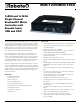

8 MDC1xxx Motor Controller Datasheet Version 1.3. January 27, 2015
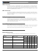
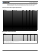
Power Stage Electrical Specifications (at 25oC ambient)
Note 1: Maximum regeneration voltage in normal operation. Never inject a DC voltage from a battery or other fixed source
Note 2: Non-condensing
TABLE 4.
Parameter Measure point Model Min Typ Max Units
Battery Leads Voltage Ground to VMot MDC1230 10 (1) 30 Volts
MDC1460 10 (1) 62 Volts
Motor Leads Voltage Ground to M+, M- MDC1230 0 (1) 30 (2) Volts
MDC1460 0 (1) 62 (2) Volts
Over Voltage protection range Ground to VMot MDC1230 5 30 (4) 35 (2) Volts
MDC1460 5 50 (4) 62 (2) Volts
Under Voltage protection range Ground to VMot MDC1230 0 5 (4) 30 Volts
MDC1460 0 5 (4) 62 Volts
Idle Current Consumption VMot or Pwr Ctrl wires All 50 75 (5) 100 mA
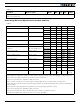
ON Resistance (Excluding wire
resistance)
VMot to M+, plus M- to
Ground at 100% power
MDC1230 6 mOhm
MDC1460 3 mOhm
Max Current for 30s Motor current MDC1230 80 (6) Amps
MDC1460 120 (6) Amps
Continuous Max Current Motor current MDC1230 50 (7) Amps
MDC1460 70 (7) Amps
Current Limit range Motor current MDC1230 1 60 (8) 80 Amps
MDC1460 1 80 (8) 120 Amps
Stall Detection Amps range Motor current MDC1230 1 60 (8) 80 Amps
MDC1460 1 80 (8) 120 Amps
Stall Detection timeout range Motor current All 1 500 (9) 65000 milli-
seconds
Motor Acceleration/Deceleration range Motor current All 100 500
(10)
65000 milli-
seconds
Note 1: Negative voltage will cause a large surge current. Protection fuse needed if battery polarity inversion is possible
Note 2: Maximum regeneration voltage in normal operation. Never inject a DC voltage from a battery or other fixed source
Note 3: Minimum voltage must be present on VMot or Power Control wire
Note 4: Factory default value. Adjustable in 0.2V increments
Note 5: Current consumption is lower when higher voltage is applied to the controller’s VMot or PwrCtrl wires
Note 6: Max value is determined by current limit setting. Duration is estimated and is dependent on ambient temperature
cooling condition
Note 7: Estimate. Limited by heatsink temperature. Current may be higher with better cooling
Note 8: Factory default value. Adjustable in 0.1A increments
Note 9: Factory default value. Time in ms that Stall current must be exceeded for detection
Note 10: Factory default value. Time in ms for power to go from 0 to 100%
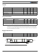
TABLE 3.
Parameter Measure point Model Min Typ Max Units