
Data Sheet
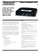

MDC1xxx Motor Controller Datasheet 7
Enabling Analog Commands
CAN Bus Operation
The controller can interface to a standard CAN Bus network, using 4 possible protocols: A simple and powerful
meshed network (RoboCAN), Standard CANOpen, and two simplified proprietary schemes (MiniCAN and Raw-
CAN). Please refer to the User Manual for details. USB and CAN cannot operate at the same time. The controller
starts up with CAN available, but CAN will be disabled as soon as the controller is plugged into USB. To re-enable
CAN, disconnect USB and restart the controller.
USB communication
Use USB only for configuration, monitoring and troubleshooting. USB is not a reliable communication method
when used in a electrically noisy environments and communication will not always recover after it is lost without
unplugging and replugging the connector, or restarting the controller. Always prefer RS232 communication when
interfacing to a computer.
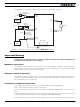
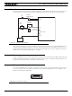
Enabling Analog Commands
For safety reasons, the Analog command mode is disabled by default. To enable the Analog mode, use the PC
utility and set Analog in Command Priority 2 or 3 (leave Serial as priority 1). Note that by default the additional
securities are enabled and will prevent the motor from starting unless the potentiometer is centered, or if the
voltage is below 0.25V or above 4.75V. The drawing shows suggested assignment of Pot 1 to ANA1. Use the PC
utility to enable and assign analog inputs.
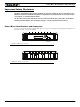
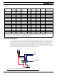
Status LED Flashing Patterns
After the controller is powered on, the Power LED will tun on, indicating that the controller is On. The Status LED
will be flashing at a 2 seconds interval. The flashing pattern provides operating or exception status information.
Additional status information may be obtained by monitoring the controller with the PC utility.
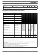
Electrical Specifications
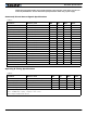
Absolute Maximum Values
The values in the table below should never be exceeded. Permanent damage to the controller may result.
TABLE 3.
Parameter Measure point Model Min Typ Max Units
Battery Leads Voltage Ground to VMot MDC1230 10 35 Volts
MDC1460 10 62 Volts
Reverse Voltage on Battery Leads Ground to VMot All -1 Volts
Motor Leads Voltage Ground to M+, M- MDC1230 30 Volts
MDC1460 62 Volts
Digital Output Voltage Ground to Output pins All 40 Volts
Analog and Digital Inputs Voltage Ground to any signal pin on 15-pin
connectors
All 15 Volts
RS232 I/O pins Voltage External voltage applied to Rx/Tx pins All 15 Volts
Board Temperature Board All -40 85 oC
Humidity Board All 100 (2) %