
Data Sheet

6 MDC1xxx Motor Controller Datasheet Version 1.3. January 27, 2015
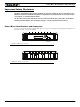
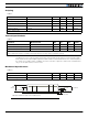
Default I/O Configuration
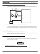
The controller can be configured so that practically any Digital, Analog and RC pin can be used for any purpose.
The controller’s factory default configuration provides an assignment that is suitable for most applications. The
figure below shows how to wire the controller to one analog potentiometer, an RC radio, and the RS232 port. It
also shows how to connect the output to a motor brake solenoid. You may omit any connection that is not
required in your application. The controller automatically arbitrates the command priorities depending on the pres-
ence of a valid command signal in the following order: 1-RS232, 2-RC Pulse, 3-None. If needed, use the Roborun+
PC Utility to change the pin assignments and the command priority order.
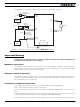
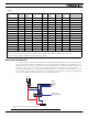
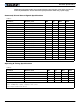
TABLE 2.
Connector
Pin Power Dout Com RC Ana Dinput Enc Default Config
1 DOUT1 Brake
9 DOUT2 Contactor
2 TxOut RS232Tx
10 RC5 ANA5 (1) DIN5 ENCA (2) Encoder (2)
3 RxIn RS232Rx
11 RC4 ANA4 DIN4 AnaCmd (3)
4 RC1 ANA1 (1) DIN1 RCRadio1
12 RC3 ANA3 DIN3 Unused
5 GND
13 GND
6 CANL CAN Low
14 5VOut
7 CANH CAN High
15 RC6 (1) ANA6 DIN6 ENCB (2) Encoder (2)
8 RC2 ANA2 DIN2 Unused
Note 1: Pin assignment for this signal may differ from other Roboteq controller models.
Note 2: Encoder input requires RC inputs 3, 4, 5 and 6 to be disabled. Encoders are enabled in factory default.
Note 3: Analog command is disabled in factory default configuration.
18
915
1
RS232
Ground
TxOut
RxIn
Motor Brake
Safety Contactor
Pot 1
RC in
FIGURE 6. Factory default pins assignment