
Data Sheet

MDC1xxx Motor Controller Datasheet 1
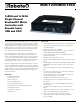
MDC1230/MDC1460
1x80A and 1x120A
Single Channel
Brushed DC Motor
Controller with
Encoder Input,
USB and CAN
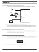
Roboteq’s MDC1230 and MDC1460 controllers are designed to
convert commands received from an RC radio, Analog Joystick,
wireless modem, PC (via RS232) or microcomputer into high
voltage and high current output for driving one DC motor. Using
CAN bus, up to 127 controllers can be networked on a single
twisted pair. Numerous safety features are incorporated into
the controller to ensure reliable and safe operation.
The controller features a high-performance 32-bit microcom-
puter and quadrature encoder inputs to perform advanced
motion control algorithms in Open Loop or Close Loop (Speed
or Position) modes. The MDC1xxx features several Analog,
Pulse and Digital I/Os which can be remapped as command or
feedback inputs, limit switches, or many other functions.
Numerous safety features are incorporated into the controller
to ensure reliable and safe operation. The controller's operation
can be extensively automated and customized using Basic Lan-
guage scripts. The controller can be reprogrammed in the field
with the latest features by downloading new operating soft-
ware from Roboteq.
Applications
• Industrial Automation
• Fan & Pump control
• Winch & Cranes
• Personal transportation
• Automatic Guided Vehicles
• Terrestrial and Underwater Robotic Vehicles
• Automated machines
• Telepresence Systems
• Animatronics
Features List
• RS232, 0-5V Analog, or Pulse (RC radio) command modes
• Auto switch between RS232, Analog, or Pulse based on
user-defined priority
• CAN bus interface at up to 1Mbit/s
• Built-in high-power power drivers for one DC motor at up
to 80A (MDC1230) and 120A (MDC1460)
• Full forward & reverse control. Four quadrant operation.
Supports regeneration
• Operates from a single power source
• Built-in programming language for automation and custom-
ization
• Programmable current limit up to 80A (MDC1230) or 120A
(MDC1460) for protecting controller, motors, wiring and
battery
• Up to 6 Analog Inputs for use as command and/or feed-
back
• Up to 6 Pulse Length, Duty Cycle or Frequency Inputs for
use as command and/or feedback
• Up to 6 Digital Inputs for use as Deadman Switch, Limit
Switch, Emergency stop or user inputs
• Quadrature Encoder input with 32-bit counter
• 2 general purpose 24V, 1A output for brake release or
accessories
• Selectable min, max, center and deadband in Pulse and
Analog modes
• Selectable exponentiation factors for each command
inputs
• Trigger action if Analog, Pulse or Encoder capture are out-
side user selectable range (soft limit switches)
• Open loop or closed loop speed control operation
• Closed loop position control with analog or pulse/fre-
quency feedback