
Data Sheet


8 MBL1xxx Motor Controller Datasheet Version 1.2. December 25, 2013
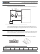
USB communication
Use USB only for configuration, monitoring and troubleshooting. USB is not a reliable communication method
when used in a electrically noisy environments and communication will not always recover after it is lost without
unplugging and replugging the connector, or restarting the controller. Always prefer RS232 communication when
interfacing to a computer.
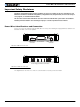
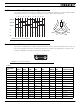
Status LED Flashing Patterns
After the controller is powered on, the Power LED will tun on, indicating that the controller is On. The Status LED
will be flashing at a 2 seconds interval. The flashing pattern provides operating or exception status information.
Additional status information may be obtained by monitoring the controller with the PC utility.
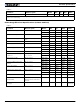
Electrical Specifications
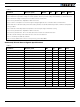
Absolute Maximum Values
The values in the table below should never be exceeded. Permanent damage to the controller may result.
TABLE 3.
Parameter Measure point Model Min Typ Max Units
Battery Leads Voltage Ground to VMot MBL1330 35 Volts
MBL1660 62 Volts
Reverse Voltage on Battery Leads Ground to VMot -1 Volts
Power Control Voltage Ground to Pwr Control wire 62 Volts
Motor Leads Voltage Ground to U, V, W wires MBL1330 30 (1) Volts
MBL1660 62 (1) Volts
Digital Output Voltage Ground to Output pins 40 Volts
Analog and Digital Inputs
Voltage
Ground to any signal pin on 15-pin &
Hall inputs
15 Volts
RS232 I/O pins Voltage External voltage applied to Rx/Tx pins 15 Volts
Case Temperature Case -40 85 oC
RS232/USB Mode
Idle - Waiting for Command
RC Pulse Mode
Analog Mode
FIGURE 9. Normal Operation Flashing Patterns
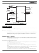
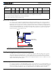
Under or Over Voltage
Power Stage Off
Short Detected
Overheat
FIGURE 10. Exception or Fault Flashing Patterns