
Data Sheet


MBL1xxx Motor Controller Datasheet 7
Enabling Analog Commands
Default I/O Configuration
The controller can be configured so that practically any Digital, Analog and RC pin can be used for any purpose.
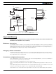
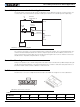
The controller’s factory default configuration provides an assignment that is suitable for most applications. The
figure below shows how to wire the controller to an analog potentiometer, an RC radio, the RS232 port, and the
Digital output to a motor brake solenoid. You may omit any connection that is not required in your application. The
controller automatically arbitrates the command priorities depending on the presence of a valid command signal
in the following order: 1-RS232, 2-RC Pulse, 3-None. If needed, use the Roborun+ PC Utility to change the pin
assignments and the command priority order.
Enabling Analog Commands
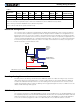
For safety reasons, the Analog command mode is disabled by default. To enable the Analog mode, use the PC
utility and set Analog in Command Priority 2 or 3 (leave Serial as priority 1). Note that by default the additional
securities are enabled and will prevent the motor from starting unless the potentiometer is centered, or if the
voltage is below 0.25V or above 4.75V. The drawing shows suggested assignment of Pot 1 to ANA1. Use the PC
utility to enable and assign analog inputs.
CAN Bus Operation
The controller can interface to a standard CAN Bus network, using 3 possible protocols: Standard CANOpen, and
two simplified proprietary schemes (MiniCAN and RawCAN). Please refer to the User Manual for details. USB and
CAN cannot operate at the same time. The controller starts up with CAN available, but CAN will be disabled as
soon as the controller is plugged into USB. To re-enable CAN, disconnect USB and restart the controller.
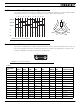
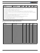
15 ANA6 DIN6 Unused
8 RC2 ANA2 DIN2 ENCB (2) Unused
Note 1: Pin assignment for this signal may differ from other Roboteq controller models.
Note 2: Encoder input requires RC inputs 1 and 2 to be disabled. Encoder is disabled in factory default.
Note 3: Analog command is disabled in factory default configuration.
Note 4: CAN can USB cannot operate simultaneously.
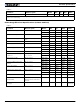
TABLE 2.
Connector
Pin Power Dout Com RC Ana Dinput Enc Default Config
18
915
1
Pot
RS232
Brake Release
Safety Contactor
Ground
TxOut
RxIn
RC Ch1
FIGURE 8. Factory default pins assignment