
Data Sheet


6 MBL1xxx Motor Controller Datasheet Version 1.2. December 25, 2013
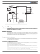
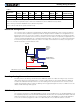
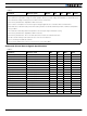
Hall Sensor vs Motor Output sequencing
The controller requires the Hall sensors inside the motor to be 120 degrees apart. The controller’s 3-phase bridge
will activate each of the motor winding according to the sequence shown in the figure below.
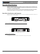
Commands and I/O Connections
Connection to RC Radio, Microcomputer, Joystick and other low current sensors and actuators is done via the 15-
pin connector located in front of the controller. The functions of many pins vary depending on controller model
and user configuration. Pin assignment is found in the table below.
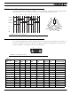
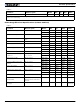
TABLE 2.
Connector
Pin Power Dout Com RC Ana Dinput Enc Default Config
1 DOUT1 Brake
9 DOUT2 Contactor
2 TxOut RS232Tx
10 ANA5 (1) DIN5 Unused
3 RxIn RS232Rx
11 RC4 ANA4 DIN4 AnaCmd (3)
4 RC1 ANA1 (1) DIN1 ENCA (2) RCRadio1
12 RC3 ANA3 DIN3 Unused
5 GND
13 GND
6 CANL (4) CAN Low
14 5VOut
7 CANH (4) CAN High
U
VW
1234561
4
2
5
3
6
4
1
5
2
6
3
Hall A
Hall B
Hall C
U
V
W
+
--
-- --
-- --
--
++ ++
++ ++
++ +
FIGURE 6. Hall Sensors sequence
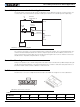
FIGURE 7. Connector pin locations
18
915