
Data Sheet

8 KBL1xxx Motor Controller Datasheet Version 1.9 May 24, 2018
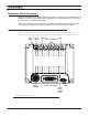
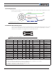
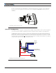
Enabling Analog Commands
For safety reasons, the Analog command mode is disabled by default. To enable the Analog mode, use the PC
utility and set Analog in Command Priority 2 or 3 (leave Serial as priority 1). Note that by default the additional
securities are enabled and will prevent the motor from starting unless the potentiometer is centered, or if the
voltage is below 0.25V or above 4.75V. The drawing shows suggested assignment of Pot 1 to ANA1. Use the
PC utility to enable and assign analog inputs.
CAN Bus Operation
The controller can interface to a standard CAN Bus network, using 4 possible protocols: Standard CANOpen, and
three proprietary schemes (MiniCAN, RawCAN and RoboCAN). Please refer to the User Manual for details.
USB communication
Use USB only for configuration, monitoring and troubleshooting. USB is not a reliable communication method
when used in a electrically noisy environments and communication will not always recover after it is lost with-
out unplugging and replugging the connector, or restarting the controller. Always prefer RS232 communication
when interfacing to a computer.
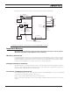
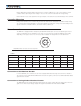
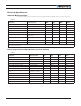
Status LEDs and Flashing Patterns
The controller is equipped with three LEDs. A Green Power LED, a Red/Green Status LED and a Yellow Com-
munication LED.
After the controller is powered on, the Power LED will tun on, indicating that the controller is On. The Status
LED will be flashing at a two second interval. The flashing pattern and color provides operating or exception
status information.
RS232/USB Mode
Idle - Waiting for Command
RC Pulse Mode
Analog Mode
Under or Over Voltage
Power Stage Off
Short Detected
Overheat
FIGURE 8. Normal Operation Flashing Patterns
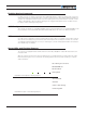
RS232/USB Mode
Idle - Waiting for Command
RC Pulse Mode
Analog Mode
Under or Over Voltage
Power Stage Off
Short Detected
Overheat
FIGURE 9. Exception or Fault Flashing Patterns