
Data Sheet

6 KBL1xxx Motor Controller Datasheet Version 1.9 May 24, 2018
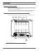
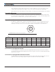
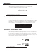
Connecting Resolver
Resolver wiring is similar to a Sin/Cos sensor with the addition of an excitation signal. Diagram below shows
the necessary connections.
Primary
Secondary 1
ASIN
ACOS
EXC
GND
Secondary 2
FIGURE 4. Resolver wiring
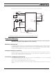
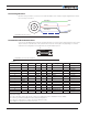
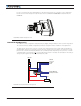
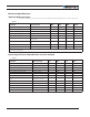
Commands and I/O Connections
Connection to RC Radio, Microcomputer, Joystick and other low current sensors and actuators is done via the
15-pin connector located in front of the controller. The functions of many pins vary depending on controller
model and user configuration. Pin assignments are found in Table 2, below.
18
915
FIGURE 5. Connector Pin Locations
TABLE 2.
Connector Pin Power Dout Com RC Ana Dinput Enc Default Config
1 DOUT1 (1) Unused
9 DOUT2 (1)(6) Brake
2 TxOut RS232Tx
10 RC ANA5 DIN5/STO1 (6) AnaCmd (3)
3 RxIn RS232Rx
11 485- RC4 ANA4 DIN4 Unused
4 RC1 ANA1 DIN1 ENCA (2) RCRadio1
12 485+ RC3 ANA3 DIN3 Unused
5 GND
13 GND
6 CANL CAN Low
14 5VOut
7 CANH CAN High
15 RC6 ANA6 DIN6/STO2 (6) Unused
8 RC2 ANA2 DIN2 ENCB (2) Unused
Note 1: Outputs are Open Drain. They pull to ground when on and float when off. Load must be connected between output
and positive voltage.
Note 2: Encoder input requires RC inputs 1 and 2 to be disabled. Encoder is disabled in factory default.
Note 3: Analog command is disabled in factory default configuration.
Note 5: Remove STO Jumper to enable Safe Torque Off functionality
Note 6: DOUT2 is replicated on the M12 connector