
Data Sheet

Motor Sensor Connector
KBL1xxx Motor Controller Datasheet 5
Note 4: Optionally ground the VMot input when the controller is Off if there is any concern that the motors
could be made to spin and generate voltage in excess of the controller’s absolute max voltage rating.
Note 5: Beware not to create a path from the ground pins on the I/O connector and the battery minus terminal.
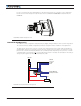
Controller Mounting
During motor operation, the controller will generate heat that must be dissipated. The published amps rating
can only be fully achieved if adequate cooling is provided. Good conduction cooling can be achieved by mount-
ing the controller to a metallic surface, such as the chassis, cabinet, etc.
Motor Sensor Connector
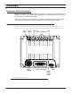
The KBL1xxx is equipped with a waterproof, standard M12 female 8-pin connector for attaching the motor’s
sensors, temperature sensor, and brake. Four of the connector’s pins are assigned a different functionality
depending on the type of sensor use for rotor position feedback. Pin assignment is in the table below.
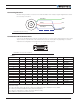
FIGURE 3. Motor Sensors Connector top view
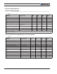
TABLE 1.
Pin Number 1 2 3 4 5 6 7 8
Hall 5VOut Hall A Hall B Hall C NC Temp Brake (1) GND
SSI 5VOut Clock+ Data+ Clock- Data- Temp Brake (1) GND
Sin/Cos 5VOut NC SIN NC COS Temp Brake (1) GND
Resolver 5VOut NC SIN NC COS EXC Brake (1) GND
Note 1: Open Drain Output. Same as DOUT2 on Dsub connector
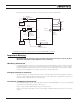
Connection to SSI Absolute Encoder
In Sinusoidal Mode, the controller can use motors equipped with absolute angle sensors with SSI interface.
The controller issues an RS422-level differential Clock+/Clock- signal to, and receives a differential Data+/Data-
signal from the encoder.
Connection to Analog Sin/Cos Absolute Encoder
The KBL1XXX has two high-speed analog inputs that can be used to capture absolute angle position from an-
gular sensors with sin/cos voltage outputs. The signal must be 0-5V max with the 0 at 2.500V.