
Data Sheet
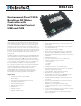

10 KBL1xxx Motor Controller Datasheet Version 1.9 May 24, 2018
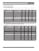
Electrical Specifications
Absolute Maximum Values
The values in Table 3, below, should never be exceeded. Permanent damage to the controller may result.
TABLE 3.
Parameter Measure point Min Typ Max Units
Battery Leads Voltage Ground to VMot 62 Volts
Reverse Voltage on Battery Leads Ground to VMot -1 Volts
Power Control Voltage Ground to Pwr Control wire 62 Volts
Motor Leads Voltage Ground to U, V, W wires 62 (1) Volts
Digital Output Voltage Ground to Output pins 40 Volts
Analog and Digital Inputs Voltage Ground to any signal pin on 15-pin
& Hall inputs
30 Volts
RS232 I/O pins Voltage External voltage applied to Rx/Tx
pins
30 Volts
Case Temperature Case -40 85 ºC
Humidity Case 100 (2) %
Note 1: Maximum regeneration voltage in normal operation. Never inject a DC voltage from a battery or other fixed source
Note 2: Non-condensing
Power Stage Electrical Specifications (at 25ºC ambient)
TABLE 4.
Parameter Measure point Min Typ Max Units
Battery Leads Voltage Ground to VMot 0 (1) 62 Volts
Motor Leads Voltage Ground to U, V, W wires 0 (1) 62 (2) Volts
Power Control Voltage 0 (1) 65 Volts
Minimum Operating Voltage 9 (3) Volts
Over Voltage protection range Ground to VMot 5 60 (4) 62 Volts
Under Voltage protection range Ground to VMot 0 5 (4) 62 Volts
Idle Current Consumption VMot or Pwr Ctrl wires 50 100 (5) 150 mA
ON Resistance (Excluding wire resis-
tance)
VMot to U, V or W.
Ground to U, V or W
1. 5 mOhm
Max Current for 60s Motor current 120 (6) Amps
Continuous Max Current per channel Motor current 100 (7) Amps
Current Limit range Motor current 10 100 (8) 120 Amps
Stall Detection Amps range Motor current 10 120 (8) 120 Amps
Stall Detection timeout range Motor current 1 65000 (9) 65000 milliseconds