
Data Sheet

Sinusoidal Commutation
Advanced Digital Motor Controller User Manual 99
Sinusoidal Commutation
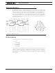
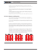
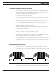
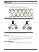
In sinusoidal commutation, all three wires are permanently energized with a sinusoidal
current that is 120 degrees apart on each phase as shown in figure 8-7.
1
11
21
31
41
51
61
71
81
91
101
111
121
131
141
151
161
171
181
191
201
211
221
231
241
251
261
271
281
291
301
311
321
331
341
351
361
371
381
391
401
411
421
431
441
451
461
471
481
491
501
511
521
531
541
551
561
571
581
591
601
611
621
631
641
651
661
671
681
691
701
711
V
U
W
Figure 8-7. 3 phase current
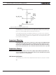
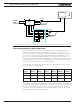
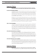
As the motor turns, the phase on each wire is changed in order for the magnetic field to
always be perpendicular, and therefore create the maximum radial force to the rotor.
90
o
90
o
Figure 8-8. Magnetic field perpendicular to rotor magnets
The principle benefit of sinusoidal commutation is the quiet, rumble-free, motor operation
resulting from the smoothly rotating and always aligned magnetic field.
Wiring Order
The angle sensing direction must match the rotating direction of the magnetic field gener-
ated by the UVW coils. If the motor does not spin and the sensors are correctly attached
and calibrated, either change the SWD configuration command (see “SWD” in the com-
mand reference section), or swap to motor wires. Note that is will typically be necessary
to adjust the angle sensor’s 0 degree reference.
Angle Feedback Sensors
In order for the proper voltage and phase to be applied to each of the 3 motor wires, the
rotor angular position must be known with precision at all times. Roboteq controllers sup-
port several techniques to achieve this.