
Data Sheet
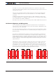
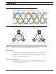

Trapezoidal Switching
Advanced Digital Motor Controller User Manual 97
Important Notice
Beware that while only one combination is valid, there may be other combinations
that will cause the motor to spin. When the motor spins with the wrong wiring
combination, it will do so very inefficiently. Make sure that the motor spins equally
smoothly in both directions. Try all 6 combinations and select the best.
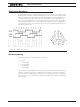
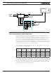
Sensorless Trapezoidal Commutation
Some Roboteq controller models support sensorless trapezoidal commutation. As the
name implies, the commutation is also made by applying current on two or the 3 motor
wires in alternating manner. However, no hall or other sensor is used on the motor to tell
the controller when to switch the phases. Instead, the rotor position is sensed by mea-
sure the motor’s back EMF voltage on the one wire that is not energized at any one time
(floating wire) during commutation. This technique is very effective and results in commu-
tation characteristics and performance practically identical to switching using Hall sensors
at medium and high speed.
Since it depends on the presence of back EMF – ie the voltage that is generated inside
the motor windings as the rotor turns in the permanent magnets field – position can only
be sensed if the rotor is spinning in the first place. The rotor position cannot be known
when the motor is stopped or stalled. In Trapezoidal Sensorless, the motor is therefore
started by applying an arbitrarily rotating field to the motor windings, making the rotor turn
similarly to stepper motors. Once the motor has started to turn and achieve a speed suffi-
cient to generate a detectable back EMF, the commutation is synchronized with the rotor
position. For all practical purposes, therefore, Sensorless Trapezoidal is not usable in any
system requiring precise control at slow speed, or high torque at stall or start.
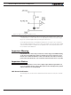
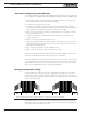
Setting and Operating Trapezoidal Modes
Trapezoidal modes are selected via using the Switching Mode configuration menu in the
Roborun PC utility, or by sending the configuration command.
^BMOD ch 0 for hall sensor commutation
^BMOD ch 2 for sensorless commutation
No other settings are necessary for the motor to run.
In the hall sensor mode, and if the sensor vs phase wiring is correct (see “Hall Sensor
Alignment and Wiring Order” on page 95), motor will spin as soon as a power com-
mand is given.
In the sensorless mode the motor will spin regardless of the phase wiring order. If the
motor spin in the opposite direction than the one desires, swap any two of the motor
wires.
The number of poles setting is not necessary in order for the motor to run. The number
of poles is only used to measure the motor’s rotation speed. Enter a negative number of
poles in order to change the speed polarity and count direction.