
Data Sheet

Brushless Motor Connections and Operation
94 Advanced Digital Motor Controller User Manual V1.8, August 28, 2017
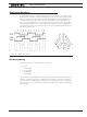
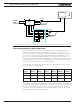
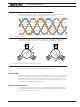
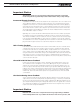
Figure 8-3. Hall sensor inputs equivalent circuit
Both 60 degrees and 120 degrees Hall sensors spacing, are supported (see “HPO” in the
command reference section). Hall sensors can typically be powered over a wide voltage
range. The controller supplies 5V for powering the Hall sensors.
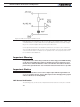
Unless specified otherwise in the datasheet, Hall sensor connection to the controller is
done using Molex Microfit 3.0 connectors. These high quality connectors provide a reliable
connection and include a lock tab for secure operation. The connector pinout is shown in
the controller model’s datasheet.
Important Warning
Keep the Hall sensor wires away from the motor wires. High power PWM switching
on the motor leads will induce spikes on the Hall sensor wires if located too close.
On hub motors where the Hall sensor wires are inside the same cable as the motor
power wires, separate the two sets of wires the nearest from the motor as possible.
Important Notice
Make sure that the motor sensors have a digital output with the signal either at 0
or at 1, as usually is the case. Sensors that output are slow changing analog signals
will cause the motor to run imperfectly.
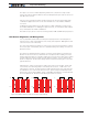
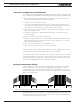
Hall Sensor Verification
The following query can be used to verify that the hall sensors are seen by the controller:
?HS