
Data Sheet

Brushless Motor Connections and Operation
92 Advanced Digital Motor Controller User Manual V1.8, August 28, 2017
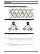
As the name implies, Brushless motors differ from traditional DC motors in that they do
not use brushes for commutating the electromagnets. Instead, it is up to the motor con-
troller to apply, in sequence, current to each of the 3 motor windings in order to cause the
rotor to spin. There are fundamentally two methods of generating the rotating magnetic
field in the motor’s winding:
• Trapezoidal Commutation
• Sinusoidal Commutation
Within each commutation method is then a method for detecting the actual position of
the rotor in order to synchronize the generated rotating field. These are:
• Hall sensors
• Encoders (Absolute or relative)
• Sensorless
All Roboteq brushless controllers support Trapezoidal with Hall sensor feedback. Sinusoidal
and alternative rotor detection techniques are available on selected models. Refer to the
controller’s datasheet to determine which modes are supported.
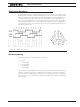
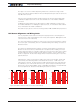
Number of Poles
One of the key characteristics of a brushless motor is the number of poles of permanent
magnets pairs it contains. A full 3-phase cycling of motor’s electromagnets will cause the
rotor to move to the next permanent magnet pole. A full 3-phase cycle is known as electri-
cal turn which will be different from the physical (mechanical) turn of the shaft if the motor
number of pole pairs is greater than one: increasing the number of pole pairs will cause
the motor to rotate more slowly for a given rate of change on the winding’s phases.
The number of pole pairs is necessary for determining the number of turns a motor has
done. It can also be used to measure the motor speed. The Roboteq controllers can
measure both.
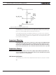
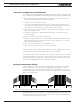
The number of pole pairs on a particular motor is usually found in the motor’s specifica-
tion sheet. The number of pole pairs can also be measured by applying a low DC current
(around 1A) between any two wires of the 3 that go to the motor and then counting the
number of cogs you feel when rotating the motor by hand for a full turn. It can also be de-
termined by rotating the motor shaft by hand a full turn. Then take the number of counts
reported by the hall counter, and divide it by 6.
The number of pole pairs is a configuration parameter that can be entered in the controller
configuration (see “BPOL” in the command reference section). This parameter is not need-
ed for basic motor operation with Hall Sensor feedback and can be left at its default value.
It is needed if accurate speed reporting is required or to operate in Closed Loop Speed
mode. The number of pole pairs in a critical configuration in sinusoidal mode.
Entering a negative number of pole pairs will reverse the measured speed and the count
direction. It is useful when operating the motor in closed loop speed mode and if other-
wise a negative speed is measured when the motor is moved in the positive direction.