
Data Sheet

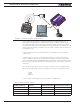

Operating the Controller in RC mode
Advanced Digital Motor Controller User Manual 77
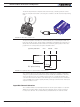
capture (one input on single channel products). Which channel and which pin on the input
connector depends on the controller model and can be found in the controller’s datasheet.
Changing the input assignment is done using the PC Configuration utility.
Input RC Channel Configuration
Internally, the measured pulse width is compared to the reference minimum, center and
maximum pulse width values. From this is generated a command number ranging from
-1000 (when the joystick is in the min. position), to 0 (when the joystick is in the center po-
sition) to +1000 (when the joystick is in the max position). This number is then used to set
the motor’ desired speed or position that the controller will then attempt to reach.
For best results, reliability and safety, the controller will also perform a series of correc-
tions, adjustments and checks to the R/C commands, as described below.
Joystick Range Calibration
The Joystick min, max and center position are adjustable. For best control accuracy, the
controller can be calibrated to capture and use your radio’s specific timing characteristics
and store them into its internal Flash memory. This is done using a simple calibration pro-
cedure described page 60.
Deadband Insertion
The controller allows for a selectable amount of joystick movement to take place around
the center position before activating the motors. See the full description of this feature at
“Deadband Selection” page 61
Command Correction
The controller can also be set to translate the joystick motor commands so that the motor
responds differently depending on whether the joystick is near the center or near the
extremes. Five different exponential or logarithmic translation curves may be applied.
Since this feature applies to the R/C, Analog and RS232 modes, it is described in detail in
“Command Correction” page 62, in the General Operation section of the manual.
Reception Watchdog
Immediately after it is powered on, if in the R/C mode, the controller is ready to receive
pulses from the RC radio.
If valid pulses are received on any of the enabled Pulse input channels, the controller will
consider the RC Pulse mode as active. If no higher priority command is currently active
(See “Input Command Modes and Priorities” page 73), the captured RC pulses will
serve to activate the motors.
If no valid RC pulses reach the controller for more than 500ms, the controller no lon-
ger considers it is in the RC mode and a lower priority command type will be accepted
if present.