
Data Sheet


Safety Recommendations
64 Advanced Digital Motor Controller User Manual V1.8, August 28, 2017
Action Output activation Typical Use
No action
Not changed by any internal controller
events.
Output may be activated using Seri-
al commands or user scripts
Motor(s) is on
When selected motor channel(s) has power
applied to it. Brake release
Motor(s) is reversed
When selected motor channel(s) has power
applied to it in reverse direction. Back-up warning indicator
Overvoltage When battery voltage above over-limit Shunt load activation
Overtemperature When over-temperature limit exceeded Fan activation. Warning buzzer
Status LED When status LED is ON
Place Status indicator in visible
location.
Encoder Configurations and Use
On controller models equipped with encoder inputs, external encoders enable a range of
precision motion control features. See “Connecting Optical Encoders” page 53 for a
detailed discussion on how optical encoders work and how to physically connect them to
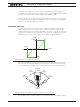
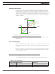
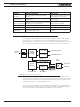
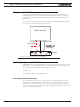
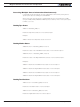
the controller. The diagram below shows the processing chain for each encoder input
32-bit
up/down
Counter
Speed
Measure
Encoder
Input
Command
Selectable Action
Selectable Action
Count
Speed in RPM
Max RPM
Feedback
Use
Select
Count > Max
Count < Min
Scalling
Encoder PPR
FIGURE 4-9. Encoder input processing
The encoder’s two quadrature signals are processed to generate up and down counts
depending on the rotation direction. The counts are then summed inside a 32-bit counter.
The counter can be read directly using serial commands and/or can be used as a position
feedback source for the closed loop position mode.
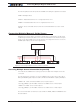
The counter can be compared to user-defined Min and/or Max values and trigger action
if these limits are reached. The type actions are the same as these selectable for Digital
Inputs and described in “Digital Inputs Configurations and Uses”page 58.