
Data Sheet

Connecting Sensors and Actuators to Input/Outputs
56 Advanced Digital Motor Controller User Manual V1.8, August 28, 2017
Cable Length and Noise Considerations
Cable should not exceed one 3’ (one meter) to avoid electrical noise to be captured by the
wiring. A ferrite core filter should be inserted near the controller for length beyond 2’ (60
cm). For longer cable length use an oscilloscope to verify signal integrity on each of the
pulse channels and on the power supply.
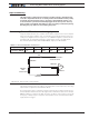
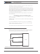
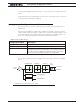
Ferrite Core
Encoder
Controller
FIGURE 3-19. Use ferrite core on cable length beyond 2’ or 60cm
Important Warning
Excessive cable length will cause electrical noise to be captured by the controller
and cause erratic functioning that may lead to failure. In such situation, stop opera-
tion immediately.
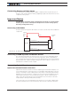
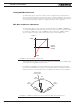
Motor - Encoder Polarity Matching
When using encoders for closed loop speed or position control, it is imperative that when
the motor is turning in the forward direction, the counter increments its value and a posi-
tive speed value is measured. The counter value can be viewed using the PC utility.
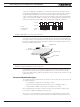
If the Encoder counts backwards when the motor moves forward, correct this by either:
1- Swapping Channel A and Channel B on the encoder connector. This will cause the en-
coder module to reverse the count direction,
2- Enter a negative number in the PPR configuration will also cause the counter to count
in the reverse direction
3- Swapping the leads on the motor. This will cause the motor to rotate in the opposite
direction.