
Data Sheet

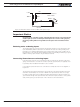

Connecting devices to Digital Outputs
Advanced Digital Motor Controller User Manual 45
Connecting devices to Digital Outputs
Depending on the controller model, 2 to 8 Digital Outputs are available for multiple pur-
poses. The Outputs are Open Drain MOSFET outputs capable of driving over 1A at up to
24V. See datasheet for detailed specifications.
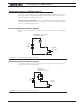
Since the outputs are Open Drain, the output will be pulled to ground when activated.
The load must therefore be connected to the output at one end and to a positive voltage
source (e.g. a 24V battery) at the other.
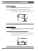
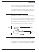
Connecting Resistive Loads to Outputs
Resistive or other non-inductive loads can be connected simply as shown in the diagram
below.
Up to
24V
DC
DOUT
Internal
Transistor
Lights, LEDs, or any other
non-inductive load
Ground
+
-
FIGURE 3-1. Connecting resistive loads to Dout pins
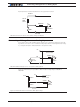
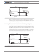
Connecting Inductive loads to Outputs
The diagrams on Figure 3-2 show how to connect a relay, solenoid, valve, small motor, or
other inductive load to a Digital Output:
Up to
24V
DC
DOUT
Internal
T
ransistor
Relay, Valve
Motor, Solenoid
or other Inductive Load
Ground
+
-
FIGURE 3-2. Connecting inductive loads to Dout pins