
Data Sheet
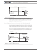

Connecting Sensors and Actuators to Input/Outputs
44 Advanced Digital Motor Controller User Manual V1.8, August 28, 2017
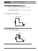
Controller’s Inputs and Outputs
The controller includes several inputs and outputs for various sensors and actuators. De-
pending on the selected operating mode, some of these I/Os provide command, feedback
and/or safety information to the controller.
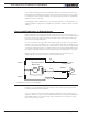
When the controller operates in modes that do not use these I/Os, these signals are
ignored or can become available via the USB/RS232 port for user application. Below is a
summary of the available signals and the modes in which they are used by the controller.
The actual number of signal of each type, voltage or current specification, and their posi-
tion on the I/O connector is given in the controller datasheet.
TABLE 3-1. Controller’s IO signals and definitions
Signal I/O type Use/Activation
DOUT1
to
DOUTn
Digital Output - Activated when motor(s) is powered
- Activated when motor(s) is reversed
- Activated when overtemperature
- Activated when overvoltage
- Mirror Status LED
- Deactivates when output stage fault
- User activated (RS232/USB or via scripting)
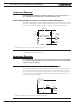
DIN1
to
DINn
Digital Input - Safety Stop
- Emergency stop
- Motor Stop (deadman switch)
- Invert motor direction
- Forward or reverse limit switch
- Run MicroBasic Script
- Load Home counter
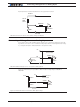
AIN1
to
AINn
Analog Input - Command for motor(s)
- Speed or position feedback
- Trigger Action similar to Digital Input if under or over
user-selectable threshold
PIN1
to
PINn
Pulse Input - Command for motor(s)
- Speed or position feedback
- Trigger Action similar to Digital Input if under or over
user selectable threshold
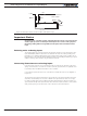
ENC1a/b
to
ENC2a/b
Encoder Inputs - Speed or position feedback
- Trigger action similar to Digital Input if under or over
user-selectable count threshold