
Data Sheet


Remote Emergency Power Disconnect
Advanced Digital Motor Controller User Manual 39
Remote Emergency Power Disconnect
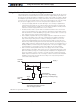
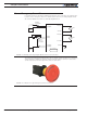
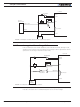
In remote controlled systems, the emergency switch must be replaced by a high power
contactor relay as shown in Figure 2-6. The relay must be normally open and be activated
using an RC switch on a separate radio channel. The receiver should preferably be pow-
ered directly from the system’s battery. If powered from the controller’s 5V output, keep
in mind that in case of a total failure of the controller, the 5V output may or may not be
interrupted.
+-
VMot
Ground
RC1
RC2
RC3
RC Switch
Controller
RC Receiver
Main
Battery
I/O Connector
PwrCtrl
On/O Switch
Ground
FIGURE 2-6 Example of remotely operated safety disconnect
The receiver must operate in such a way that the contactor relay will be off if the transmit-
ter if off or out of range.
The transmitter should have a visible and easy to reach emergency switch for the oper-
ator. That switch will be used to deactivate the relay remotely. It could also be used to
shutdown entirely the transmitter, assuming it is determined for certain that this will deac-
tivate the relay at the controller.
Protection using Supervisory Microcomputer
In applications where the controller is commanded by a PC, a microcomputer or a PLC,
that supervisory system could be used to verify that the controller is still responding and
cut the power to the controller’s power stage in case a malfunction is detected. The su-
pervisory system would only require a digital output or other means to activate/deactivate
the contactor relay as shown in the figure below.