
Data Sheet


Motor Deactivation in Case of Output Stage Hardware Failure
Advanced Digital Motor Controller User Manual 37
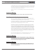
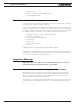
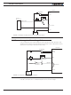
The figures below show all the possible combinations of shorted MOSFETs switches in a
brushed DC motor controller.
1
+
-
+
-
+
-
+
-
+
-
+
-
+
-
+
-
+
-
+
-
+
-
+
-
+
-
+
-
+
-
3
2
9
8
11
10
13
15 16
12
6
5
4
7
14
FIGURE 2-1. MOSFET Failures resulting in no motor activation
1
+
-
+
-
+
-
+
-
+
-
+
-
+
-
+
-
+
-
+
-
+
-
+
-
+
-
+
-
+
-
3
2
9
8
11
10
13
15 16
12
6
5
4
7
14
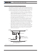
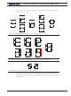
FIGURE 2-2. MOSFET Failures resulting in battery short circuit and no motor activation
1
+
-
+
-
+
-
+
-
+
-
+
-
+
-
+
-
+
-
+
-
+
-
+
-
+
-
+
-
+
-
3
2
9
8
11
10
13
15 16
12
6
5
4
7
14
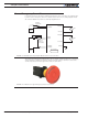
FIGURE 2-3. MOSFET Failure resulting in motor activation
Two failure conditions (15 and 16) will result in the motor spinning out of control re-
gardless whether the controller is on or off. While these failure conditions are rare, us-
ers must take them into account and provide means to cut all power to the controller’s
power stage.