
Data Sheet

Commands Reference
292 Advanced Digital Motor Controller User Manual V1.8, August 28, 2017
Analog, Digital, Pulse IO Configurations
These parameters configure the operating mode and how the inputs and outputs work.
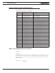
TABLE 19-6. Input/Output Configurations
Command
Arguments Description
ACTR InputNbr Center Set Analog Input Center (0) Level
ADB InputNbr Deadband Analog Deadband
AINA InputNbr Use Analog Input Use
ALIN InputNbr Linearity Analog Linearity
AMAX InputNbr Max Set Analog Input Max Range
AMAXA InputNbr Action Action at Analog Max
AMIN InputNbr Min Set Analog Input Min Range
AMINA InputNbr Action Action at Analog Min
AMOD InputNbr Mode Enable and Set Analog Input Mode
APOL InputNbr Polarity Analog Input Polarity
DINA InputNbr Action Digital Input Action
DINL ActiveLevels Digital Input Active Level
DOA OutputNbr Action Digital Output Action
DOL ActiveLevels Digital Outputs Active Level
PCTR InputNbr Center Pulse Center Range
PDB InputNbr Deadband Pulse Input Deadband
PINA InputNbr Use Pulse Input Use
PLIN InputNbr Linearity Pulse Linearity
PMAX InputNbr Max Pulse Max Range
PMAXA InputNbr Action Action on Pulse Max
PMIN InputNbr Min Pulse Min Range
PMINA InputNbr Action Action on Pulse Min
PMOD InputNbr Mode Pulse Mode Select
PPOL InputNbr Polarity Pulse Input Polarity
ACTR - Set Analog Input Center (0) Level
HexCode: 16
Description:
This parameter is the measured voltage on input that will be considered as the center or
the 0 value. The min, max and center are useful to set the range of a joystick or of a feed-
back sensor. Internally to the controller, commands and feedback values are converted to
1000, 0, +1000.
Syntax Serial: ^ACTR cc nn
~ACTR [cc]