
Data Sheet

Power Connections
Advanced Digital Motor Controller User Manual 23
SECTION 1
Connecting
Power and
Motors to the
Controller
This section describes the controller’s connections to power sources and motors.
This section does not show connector pin-outs or wiring diagram. Refer to the datasheet
for these.
Important Warning
The controller is a high power electronics device. Serious damage, including fire,
may occur to the unit, motor, wiring and batteries as a result of its misuse. Please
follow the instructions in this section very carefully. Any problem due to wiring er-
rors may have very serious consequences and will not be covered by the product’s
warranty.
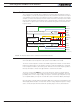
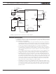
Power Connections
Power connections are described in the controller model’s datasheet. Depending on the
model type, power connection is done via wires, fast-on tabs, screw terminals or copper
bars coming out of the controller.
Controllers with wires as power connections have Ground (black), VMot (red) power ca-
bles and a Power Control wire (yellow). The power cables are located at the back end of
the controller. The various power cables are identified by their position, wire thickness and
color: red is positive (+), black is negative or ground (-).
Controllers with tabs, screw terminals or copper bars have their connector identified in
print on the controller.