
Data Sheet


Serial (RS232/USB) Operation
150 Advanced Digital Motor Controller User Manual V1.8 August 28, 2017
Serial Port Configuration
The controller’s default serial communication port is set as follows:
• 115200 bits/s
• 8-bit data
• 1 Start bit
• 1 Stop bit
• No Parity
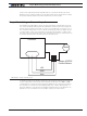
Communication is done without flow control, meaning that the controller is always ready
to receive data and can send data at any time.
Connector RS232 Pin Assignment
113
14 25
18
915
11
3
14 25
18
915
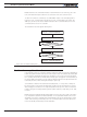
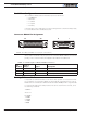
FIGURE 14-1. DB25 and DB15 connectors pin code locations
When used in the RS232 mode, the pins on the controller’s DB15 or DB25 connector (de-
pending on the controller model) are mapped as described in the table below
TABLE 14-1. RS232 Signals on DB15 and DB25 connectors §
Pin
Number
Input or
Output Signal Description
2 Output Data Out RS232 Data from Controller to PC
3 Input Data In RS232 Data In from PC
5 - Ground Controller ground
Setting Different Bit Rates
It is possible to set RS232 bit rate to lower values. This operation can only be done while
the controller is connected via USB and only using manual commands from the console.
Beware that once the bit rate is different than the default 115200, it will no longer be able
to communicate with the PC utility if serial connection is used. From the Console, send
the following commands:
^RSBR nn
where nn =
0: 115200
1: 57600
2: 38400
3: 19200
4: 9600