
Data Sheet
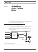

Closed Loop Count Position Mode
140 Advanced Digital Motor Controller User Manual V1.8 August 28, 2017
Sensor Types and Mounting
In position mode, best results are achieved with encoders directly mounted on the motor
shaft. Encoders can be:
• Quadrature encoders
• Hall Sensors built-in brushless motors
• Other rotor sensors built-in brushless motors
It is not advised to mount encoders at the output of a geared motor as the gear box often
introduces backlash. If the encoder must be mounted at the output, then it must typically
have a higher count to compensate the lower speed rotation at that location.
Quadrature encoders typically provide the highest resolution since they can be ordered
with line resolution of several hundreds or thousands of counts per revolution. Hall encod-
ers built in brushless motors give a relatively low, but often adequate count of 6* Number-
OfPoles per mechanical resolution. Other brushless rotor sensors, such as SPI/SSI digital
sensor, or sin/cos sensors will give up to 512 counts per pole and can therefore be used
instead of encoders.
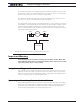
Encoder Home reference
Beware that encoders do not give an absolute position information. It is therefore neces-
sary to perform a search of the zero reference position at least once after every power up.
This is typically achieved by moving the motor up to a limit switch and loading the counter
with a fixed value at that location. A home search sequence can easily be implemented
using a MicroBasic script. The search and counter loading must be done while the motor
is operated in open loop.
Important Warning
Changing the counter with a value while the motor is operated in closed loop can
cause violent and dangerous jumps. Always revert to open loop to change the
counter value.
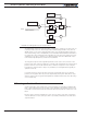
Preparing and Switching to Closed Loop
To enter this mode you will first need to configure the encoder so that it is used as feed-
back for motor1, and feedback for motor2 on the other encoder in a dual motor system.
On brushless motors, the rotor sensor (Hall, SPI, sin/cos) can be used as a position count-
er. Selecting “Other” will use the encoder if present and properly configured. Selecting
“Hall” will enable the rotor sensor.
Use the PC Utility to set the default acceleration, deceleration and position mode velocity
in the motor menu. These values can then be changed on the fly if needed.
While in Open Loop, enable the Speed channel in the Roborun Chart recorder. Move the
slider in the positive direction and verify that the measured speed polarity is also positive.
If a negative speed is reported, swap the two encoder wires to change the measured po-
larity, or swap the motor leads to make the motor spin in the opposite direction.