
Data Sheet
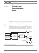

Closed Loop Relative and Tracking Position Modes
134 Advanced Digital Motor Controller User Manual V1.8 August 28, 2017
Position
End
P
osition
Star
t
P
osition
P
osition
Mode
V
elocity
Acceleration Deceleration
Speed
T
ime
T
ime
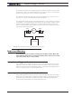
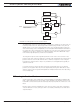
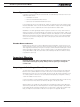
FIGURE 11-3 .
When turning the controller on, the default acceleration, deceleration and velocity are pa-
rameters retrieved from the configuration EEPROM. In most applications, these parame-
ters can be left unchanged and only change in commands used to control the change from
one position to the other. In more sophisticated systems, the acceleration, deceleration
and velocity can be changed on the fly using Serial/USB commands or from within a Mi-
croBasic script.
When using Encoders as feedback sensors, the controller can accurately measure the
speed and the number of motor turns that have been performed at any point in time. The
complete positioning algorithm can be performed with the parameters described above.
When using analog or pulse sensors as feedback, the system does not have a direct way
to measure speed or number of turns. It is therefore necessary to configure an additional
parameter in the controller which determines the number of motor turns between the
point the feedback sensor gives the minimum feedback value (-1000) to the maximum
feedback value (+1000).
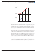
In the Closed Loop Relative Position mode, the controller will compute the position at
which the motor is expected to be at every millisecond in order to follow the desired ac-
celeration and velocity profile. This computed position becomes the setpoint that is com-
pared with the feedback sensor and a correction is applied at every millisecond.