
Data Sheet

Using Current Trigger as Protection
Advanced Digital Motor Controller User Manual 133
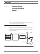
The diode polarity depends on the particular wiring and motor orientation used in the ap-
plication. If the diode is mounted backwards, the motor will not stop once the limit switch
lever is pressed. If this is the case, reverse the diode polarity.
The diodes may be eliminated, but then it will not be possible for the controller to move
the motor once either of the limit switches has been triggered.
The main benefit of this technique is its total independence on the controller’s electronics
and its ability to work in practically all circumstances. Its main limitation is that the switch
and diode must be capable of handling the current that flows through the motor. Note
that the current will flow though the diode only for the short time needed for the motor to
move away from the limit switches.
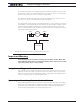
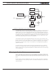
Motor
SW1 SW2
Controller
FIGURE 11-2 . Safety limit switches interrupting power to motor
Important Warning
Limit switches must be used when operating the controller in Position Mode. This
will significantly reduce the risk of mechanical damage and/or injury in case of dam-
age to the position sensor or sensor wiring.
Using Current Trigger as Protection
The controller can be configured to trigger an action when current reaches a user config-
urable threshold for more than a set amount of time. This feature can be used to detect
that a motor has reached a mechanical stop and is no longer turning. The triggered action
can be an emergency stop or a simulated limit switch.
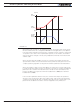
Operating in Closed Loop Relative Position Mode
This position algorithm allows you to move the motor from an initial position to a desired
position. The motor starts with a controlled acceleration, reaches a desired velocity, and
decelerates at a controlled rate to stop precisely at the end position. The graph below
shows the speed and position vs. time during a position move.