
Data Sheet

Closed Loop Relative and Tracking Position Modes
132 Advanced Digital Motor Controller User Manual V1.8 August 28, 2017
Important Warning
If there is a polarity mismatch, the motor will turn in the wrong direction and the
position will never be reached. The motor will turn until the Closed Loop Error de-
tection is triggered. The motor will then stop until the error disappears, the control-
ler is set to Open Loop, or the controller is reset.
Determining the right polarity is best done experimentally using the Roborun utility (see
“Using the Roborun Configuration Utility” on page 225) and following these steps:
1. Configure the controller in Open Loop Speed mode.
2. Configure the position sensor input channel as position feedback for the desired motor
channel.
3. Click on the Run tab.
4. Enable the Feedback channel in the chart recorder.
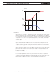
5. Move the slider slowly in the positive direction and verify that the Feedback in the chart
increases in value. If the Feedback value decreases, then the sensor is backwards
and you should either invert using configuration commands, invert the sensor physi-
cally, it or swap the motor wires so that the motor turns in the opposite direction.
6. Move the sensor off the center position and observe the motor’s direction of rotation.
7. Go to the max position and verify that the feedback value reaches 1000 a little before
the end of the physical travel. Modify the min and max limits for the sensor input if
needed.
8. Repeat the steps in the opposite direction and verify that the -1000 is reached a little
before the end of the physical travel limit.
Important Safety Warning
Never apply a command that is lower than the sensor’s minimum output value or
higher than the sensor’s maximum output value as the motor would turn forever
trying to reach a position it cannot. Configure the Min/Max parameter for the sen-
sor input so that a value of -1000 to +1000 is produced at both ends of the sensor
travel.
Adding Safety Limit Switches
The Position mode depends on the position sensor providing accurate position informa-
tion. If the sensor is damaged or one of its wires is cut, the motor may spin continuously
in an attempt to reach a fictitious position. In many applications, this may lead to serious
mechanical damage.
To limit the risk of such breakage, it is recommended to add limit switches that will
cause the motor to stop if unsafe positions have been reached independent of the sen-
sor reading. Any of the controller’s digital inputs can be used as a limit switch for any
motor channel.
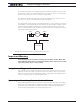
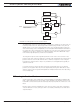
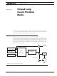
An alternate method is shown in Figure 11-2. This circuit uses Normally Closed limit
switches in series on each of the motor terminals. As the motor reaches one of the
switches, the lever is pressed, cutting the power to the motor. The diode in parallel with
the switch allows the current to flow in the reverse position so that the motor may be re-
started and moved away from that limit.