
Data Sheet
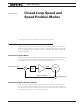

Closed Loop Relative and Tracking Position Modes
130 Advanced Digital Motor Controller User Manual V1.8 August 28, 2017
This mode requires fewer settings but often results in a motion that is not as smooth and
harder to control overshoots.
Selecting the Position Modes
The two position modes are selected by changing the Motor Control parameter to Closed
Loop Position. This can be done using the corresponding menu in the Power Output tree
in the Roborun utility. It can also be done using the associated serial (RS232/USB) com-
mand. See “MMOD” on page 329. The position mode can be set independently for each
channel.
Position Feedback Sensor Selection
The controller may be used with the following kinds of sensors:
• Potentiometers
• Hall effect angular sensors
• Optical Encoders
• Hall sensor in brushless motor
The first two are used to generate an analog voltage ranging from 0V to 5V depending on
their position. They will report an absolute position information at all times.
Modern position Hall sensors output a digital pulse of variable duty cycle. These sensors
provide an absolute position value with a high precision (up to 12-bit) and excellent noise
immunity. PWM output sensors are directly readable by the controller and therefore are a
recommended choice.
Optical encoders report incremental changes from a reference which is their initial posi-
tion when the controller is powered up or reset. Before they can be used for reporting po-
sition, the motors must be moved in open loop mode until a home switch is detected and
resets the counter. Encoders offer the greatest positional accuracy possible.
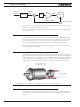
Sensor Mounting
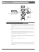
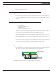
Proper mounting of the sensor is critical for an effective and accurate position mode oper-
ation. Figure 11-1 shows a typical motor, gear box, and sensor assembly.
Position Sensor
Gear box
Position Feedback
FIGURE 11-1. Typical motor/Potentiometer/assembly in Position Mode