
Data Sheet


AC-induction-Motor-Operation
114 Advanced Digital Motor Controller User Manual V1.8, August 28, 2017
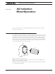
• They are maintenance free motors unlike dc motors due to the absence of brushes,
commutators and slip rings.
• Induction motors can be operated in polluted and explosive environments as they do not
have brushes which can cause sparks
Asynchronous Rotation and Slip
AC Induction motors are Asynchronous Machines meaning that the rotor does not turn at
the exact same speed as the stator’s rotating magnetic field. Some difference in the rotor
and stator speed is necessary in order to create the induction into the rotor. The difference
between the two is called the slip.
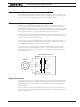
Slip is measured in Hertz. It is the difference of the frequency generated by the controller,
and the rotor’s frequency, as determined by the formula
f = ((RPM / 60) * NumberOfPoles)
Optimal slip varies from motor to motor and is in the range of typically 2 to 10Hz.
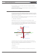
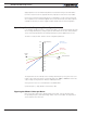
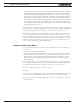
As seen from the figure below, when the slip is 0, i.e. the rotor turns at exactly the same
speed as the stator field, torque totally disappears. Within the stable operating region,
the Torque is proportional to the Slip. The torque and motor efficiency then quickly drops
when the slip grows past its optimal value.
Torque
(Produced on Motor Shaft)
Torque
(Applied to Generator Rotor)
Stable
Region
Motoring
Generating
Synchronous Speed
Slip = 0
Torque = 0
Stable
Region
Slip (Hz)
Rotor Speed
(RPM)
0
0 RPM
The main task of the motor controller is to generate a rotating magnetic field whose
frequency and strength is such that the rotor will operate within the motor’s optimal slip
range. Three techniques are supported by Roboteq for a achieving this:
Scalar, Volts per Hertz (VPH)
Constant Slip
Field Oriented Control
Each of these techniques, benefits and limitations are described in following sections