
Data Sheet

Field Oriented Control (FOC)
Advanced Digital Motor Controller User Manual 109
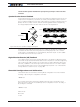
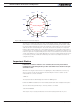
As can be seen in figure 8-10, when the magnetic field is at an angle other than exactly
perpendicular to the rotor’s magnets, the rotor is pulled by a force that can be decom-
posed in two forces:
Lateral force causing torque, and therefore rotation. This force results from the from the
Quadrature current Iq, which is also called Torque current
Parallel force that pulls the rotor outwards, creating no motion. This force results from the
Direct Current Id, which is also called Flux current
Field Oriented Control is a technique that measures the useful Torque current and wasted
Flux current component of the motor current. It then automatically adjust the power and
phase applied to each motor wire in order to eliminate the wasted Flux current
Id
PI Regulator
PI Regulator
Iq
Inverse
Park
SVPWM
Clarke
MOSFET
Bridges
Angle
Capture
Park
i
a
i
b
i
α
i
β
i
q
i
d
i
q
i
d
v
q
v
d
v
α
v
β
-
-
θ
Motor
Sensor
Desired Torque
Current
Desired Flux
Current
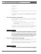
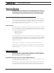
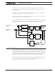
Figure 8-11. FOC operation
Field Oriented Control is available on selected models of Roboteq motor controllers. It is
uses a classical implementation as described in the figure 8-11. The current in the motor
phase is captured, along with the rotor’s angle. From this are computed the useful Iq and
wasteful Iq. Two Proportional-Integral (PI) regulators then work to control the power output
so that the desired Torque (Iq) and Flux (Id) currents are met. The desired Flux current is
typically set to 0, and so the regulator will work to totally eliminate the Flux current.
Both PI regulator have user-settable gains. While the factory default gains are suitable for
most motors and applications, they can be modified with the FOC Parameters in the PC
utility. They can also be changed with the console command: