
Data Sheet


Brushless Motor Connections and Operation
108 Advanced Digital Motor Controller User Manual V1.8, August 28, 2017
sion motors, this results in a stable speed being reported. On less elaborate motors, such
as low-cost hub motors, the reported speed may oscillate by a few percent.
Speed measurement is very precise with digital absolute sensors (SPI). Sin/Cos sensors
operating without noise also give a very precise value.
The motor’s number of poles must be entered as a controller parameter in order to pro-
duce an accurate RPM value. See discussion above. The speed information can then be
used as feedback in a closed loop system. Motor with a more precise Hall sensor posi-
tioning will work better in such a configuration than less precise motors.
If the reported speed is negative when the slider is moved in the positive direction, you
can correct this by putting a negative number of poles in the motor configuration. This will
be necessary in order to operate the motor in closed loop speed mode using hall sensor
speed capture.
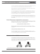
Distance Measurement using Hall, SPI or other Sensors
When Hall sensors are used, the controller automatically detects the direction of rotation,
keeps track of the number of Hall sensor transition and updates a 32-bit up/down counter.
The number of counts per revolution is computed as follows:
Counts per Revolution = Number of Poles * 6
With SPI or Sin/Cos sensors, the controller accumulates the angle data to recreate an
accurate and high resolution 32-bit counter. For these sensors, the number of counts per
revolution is:
Counts per Revolution = Number of Poles * 512
The counter information can then be read via the Serial/USB port, CAN bus, or can be
used from a MicroBasic script. The counter can also be used to operate the brushless mo-
tor in a Closed Loop Position mode, within some limits.
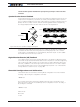
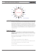
Field Oriented Control (FOC)
In sinusoidal modes, using the rotor angle to determine the voltage to apply to each of
the 3 motor phase works well at low frequencies, and therefore at low rotation speed. At
higher speed, the effect of the winding inductance, back EMF and other effect from the
motor rotation, create a shifting current. The resulting magnetic field is then no longer op-
timally perpendicular to the rotor’s permanent magnets.
I = Iq
I
Iq
Id
Figure 8-10. Perpendicular and non-perpendicular fields