
Data Sheet

Operating Brushless Motors
Advanced Digital Motor Controller User Manual 107
Important Warning
In version 1.5 and lower of the firmware, the Zero Adjust Offset was stored in the
configuration flash. The value will be lost, and a new calibration must be performed
when installing version 1.6 of the firmware. In version 1.6 and newer, the value is
stored in a dedicated section of Flash and will not be lost after firmware updates.
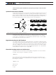
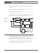
Operating Brushless Motors
Once the Hall sensors, motor power wires, and/or the Encoder are correctly connected
to the controller, a brushless motor can be operated exactly like a DC motor and all other
sections in this manual are applicable. In addition, the Hall sensors or encoders, provide
extra information about the motor’s state compared to DC motors. This information en-
ables the additional features discussed below.
Stall Detection
The Hall sensors and the encoders can be used to detect whether the motor is spinning
or not. The controller includes a safety feature that will stop the motor power if no rotation
is detected while a given amount of power is applied for a certain time. Three combina-
tions of power and time are available:
• 250ms at 10% power
• 500ms at 25% power
• 1s at 50% power
If the power applied is higher than the selected value and no motion is detected for the
corresponding amount of time, the power to the motor is cut until the motor command is
returned to 0. This function is controlled by the BLSTD - Brushless Stall Detection param-
eter (see “BLSTD - Brushless Stall Detection” in Command Reference section). Do not
disable the stall protection.
A stall condition is indicated with the “Stall” LED on the Roborun PC utility screen.
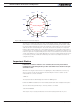
In Trapezoidal modes using Hall sensors, the Stall detection looks for changes at any of
the Hall sensors inputs. In Sinusoidal modes, the detection uses the speed measurement
from the encoders.
Important Notice
In close loop modes, it is quite possible to have the motor stopped while power is
applied to them. That could happen while stopped uphill, for example. Select the
appropriate triggering level for your application
Speed Measurement using the angle feedback Sensors
Information from Hall, SPI, sin/cos sensors, (and even Sensorless) is used by the control-
ler to compute the motor’s rotation speed.
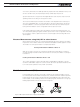
When Hall sensors are used, speed is determined by measuring the time between Hall
sensor transitions. This measurement method is very accurate, but requires that the mo-
tor be well constructed and that the placement between sensors be accurate. On preci-