
Data Sheet

Brushless Motor Connections and Operation
104 Advanced Digital Motor Controller User Manual V1.8, August 28, 2017
values using ASI query. Verify that these value do change as the shaft is turned and that
have a difference between the min and max values of at least 1000.
Once the sensor is verified to be working, a one-time calibration must be performed to
captures the mechanical offset of the sensor. In most cases, a small difference exists be-
tween the 0 degrees from the sensor vs the actual 0 degrees of the motor. Verify that the
motor shaft is rotating freely. Then perform a Zero Angle reference search.
Single Pole vs Multi Pole Sin/Cos sensors
Some sin/cos sensors will produce a full 360 degrees output for each full 360 mechanical
turns. These are single pole sensors. Other sensors have multiple poles, meaning that the
sine or cosine signal will perform two or more full 360 degrees cycles for every mechani-
cal cycles. The number of sensor poles is a critical configuration parameter which must be
set using the Sensor Poles menu. It can also be set from the console or serial port with
^SPOL ch poles
You can determine the number of sensor poles by following these steps:
1 After calibrating the sensor, set Motor Poles to 1 (^BPOL 1 1) and the Set Sensor Poles
to 1 (^spol 1 1).
2 Make one full rotation of the motor shaft by hand and monitor Angle in Roborun Utility.
3 Check how many times the Angle range (0-511) rolls over. This gives the number of sen-
sor poles.
4 Restore the correct values of motor and sensor poles
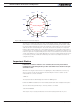
Sinusoidal Zero-Angle Reference Search Process
Most angle sensors will not give an accurate absolute position of the rotor. Incremental
encoder give relative position by their nature and must be set with a reference angle at
every power up.
Absolute sensors like SPI, resolvers or Sin/Cos are not always mounted with a precise ze-
ro-degree reference and must be calibrated at least once.
A reference search can be initiated manually by sending the serial command:
!BND 1 for channel 1
!BND 2 for channel 2
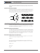
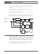
The controller will then respond by energizing the U, V and W coils with the voltages lev-
els needed to force the rotor to move to predetermined positions. The sequence is +90,
-90, +90, -90, +90 and back to -90 electrical degrees. The reference search is considered a
success if the rotor correctly reached the last four end position.
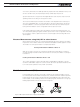
For the reference search to work, the motor must be free to move at least a full electrical
turn (mechanical turn divided by the number of pole pairs). If a brake is present, it must be
disengaged during the search sequence.