
Data Sheet
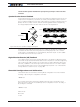
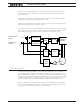

Sinusoidal Commutation
Advanced Digital Motor Controller User Manual 103
Setup and Test the SPI Encoder Feedback Mode
SPI encoders give an absolute angle in digital form, serially to the controller. These sen-
sors can be trusted to give an accurate angle measurement. However, they typically are
not perfectly mechanically aligned with the motor’s zero degree reference. Therefore a
one-time reference calibration must be performed.
After enabling the Sinusoidal Mode and SPI Angle Feedback, verify first that the Hall
Counter (which is shared in this case with the SPI sensor), displays a stable number that
is different from zero. This will indicate that data is output from the sensor and captured
by the controller. Rotate the motor by hand to verify that the counter changes.
Typically, SPI encoders are single pole, meaning that they give the angle value within one
full mechanical turn. A multiple pole sensor would measure multiple full 360 degrees for
every mechanical cycles. The number of sensor poles is a critical configuration parameter
which must be set using the Sensor Poles menu. It can also be set from the console or
serial port with
^SPOL ch poles
Setup and Test the Sin/Cos Encoder Feedback Mode
Sin/Cos encoders are absolute devices. A one-time setup and calibration must be per-
formed in order to calibrate the encoder’s voltage levels, and set the mechanical zero de-
gree angle offset.
The first calibration step measures and stores the minimum and maximum voltages of the
encoder’s signals at of each of the controller’s inputs:
After the controller is configured in Sinusoidal mode with Sin/Cos Feedback, from the con-
sole, type:
%CLMOD 2 for motor channel 1
%CLMOD 3 for motor channel 2
This will cause the controller to enter the calibration mode. Move the shaft of the motor
slowly by hand in order to make a couple of full mechanical turns.
Then press %CLMOD 0 (for either motor channels) in order to get out of the calibration mode.
Pressing the command ~ZSMC you can see the calibration values (3 first values for motor
1 and the other 3 for motor 2). Verify that the values are different than 0.
In order to save the calibration values permanently to flash type
%CLSAV 321654987.
You can verify that the sensor works, enable the Angle capture in the Roborun chart. Then
move the shaft by hand and verify that the reported angle smoothly ramps from 0 to 511
(512 = 360 electrical degrees). For additional help, you can verify that the sensor signals
are received by the controller. Move the motor shaft by hand and check the sin/cos raw