
Data Sheet
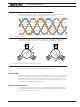

Brushless Motor Connections and Operation
100 Advanced Digital Motor Controller User Manual V1.8, August 28, 2017
Important Notice
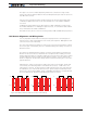
The number of poles is a very important configuration parameter in sinusoidal
mode. Using the wrong value will produce erratic behavior and possibly damage.
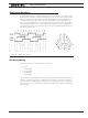
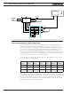
Incremental Encoder Feedback
A quadrature encoder can be used to determine the rotor position. Since encoders do not
give an absolute position, a reference search sequence is necessary before any power
is applied to the motor. The controller will automatically perform this search by applying
a fixed amount of power between the U and V outputs to pull the rotor to the known po-
sitions. This reference search is done at power up or whenever the mode is switched to
Sinusoidal with Encoder feedback. The search can also be initiated from the serial port or
from a MicroBasic script. See below.
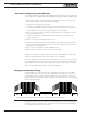
Optimally, the encoder should have a PPR that is at least 128 x the number of pole pairs.
For example a motor with 4 pole pairs should have a 128 x 4 = 512 Pulse per revolution.
This will result in 2048 counts for a full turn of the rotor, and therefore the electrical angle
to be measured with 360 / 2048 * 4 = 0.7 degrees, resulting in a very smooth changing
sinusoidal drive to the motor. A significantly lower resolution encoder will results in a step-
ping sinusoid. A higher resolution encoder will not improve the waveform.
Hall + Encoder Feedback
If the motor is fitted with Hall sensors and an Incremental Encoder, the controller can be
configured to use both sensors together. In this mode, the operating mode is identical
to when an Encoder alone is used for feedback, except that there is no need for the ref-
erence search sequence described above. When first energized, the motor will operate
using the Hall sensor until the first change to the Hall pattern is detected. This will set the
angle reference for the encoder. For this mode, it is critical that both the number of En-
coder PPRs and the motor number of pole pairs be entered correctly. Both counters must
count in the same direction.
Sinusoidal with Hall Sensor Feedback
In this mode, the Hall sensors are used to determine the angular position of the rotor.
Since transitions of the Hall pattern occur at every 60 degrees only, the controller will
estimate the current angle by interpolating in between two transition based on the cur-
rent motor speed. This technique works well as long as speed is stable and changes are
relatively slow. It also requires that the magnets and sensors are positioned with precision
inside the motor, which is not always the case in low cost motors. Compared to Trape-
zoidal mode, this mode will result is quieter motor operation because of the sinusoidal
commutation.
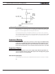
Sine/Cosine Analog Sensor Feedback
Some controller models can be interfaced to absolute position sensors with sine/cosine
output. These sensors are usually made using Hall technology, or resolvers, and are built
into the motor. They provide two analog voltage output that are 90 degrees apart. The an-
gle is determined by measuring the voltage ratio between the two signals. The controller
can compensate for differences in amplitudes between the two signals. Sin/cos sensors
require a one-time setup and calibration.
Important Notice
Electrical noise on the sensor output will cause wrong angle readings. Shield the
wires and keep them as far as possible from the motor wires. If noise persists, add