
Data Sheet
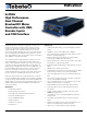

6 HDC24xx Motor Controller Datasheet Version 1.5. October 12, 2015
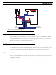
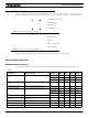
Sensor and Commands Connection
Connection to RC Radio, Microcomputer, Joystick and other low current sensors and actuators is done via the 25
and 9 pin connectors located in front of the connector. The functions of many pins vary depending on controller
model and user configuration. Pin assignment is found in the table below.
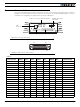
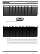
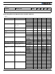
TABLE 4.
Connector Pin Power Dout Com Pulse Ana Dinput Enc Default Config
1 GND
14 5VOut
2 TxData RS232Tx
15 RC1 ANA1 DIN1 RCRadio1
3 RxData RS232Rx
16 RC2 ANA2 DIN2 RCRadio2
4 RC3 ANA3 DIN3 AnaCmd1 (1)
17 RC4 ANA4 DIN4 AnaCmd2 (1)
5 GND
18 DOUT1 DIN12 Motor Brake 1
6 DOUT2 DIN13 Motor Brake 2
19 DOUT3 DIN14 Safety Contactor
7 DOUT4 DIN15 Unused
20 DOUT5 DIN16 Unused
8 DOUT6 DIN17 Unused
21 ANA5 DIN5 Unused
9 GND
22 ANA6 DIN6 Unused
Auxiliary Connector
(Reserved)
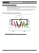
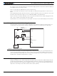
USB connect, Power and Status LEDs
FIGURE 4. Front Controller Layout
Communication and I/O Connectors
USB
Connector
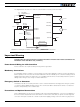
113
14 25
FIGURE 5. Main Connector pin locations