
Data Sheet

HDC24xx Motor Controller Datasheet 5
Use of Safety Contactor for Critical Applications
the controller. Some controllers already out in the field will not apply, but all recent purchases made from Roboteq
as of 10/2/15 will have this change in effect
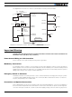
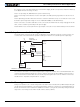
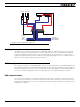
Note 2: Use precharge 1K, 0.5W Resistor to prevent switch arcing.
Note 3: Insert a high-current diode to ensure a return path to the battery during regeneration in case the fuse is
blown.
Note 4: Optionally ground the VMot wires when the controller is Off if there is any concern that the motors could
be made to spin and generate voltage in excess of 50V (HDC2450(S)) or 75V (HDC2472(S)).
Note 5: Connect the controller’s earth tab to a wire connected to the Earth while the charger is plugged in the AC
main, or if the controller is powered by an AC power supply.
Note 6: Beware not to create a path from the ground pins on the I/O connector and the battery’s minus terminal.
Use of Safety Contactor for Critical Applications
An external safety contactor must be used in any application where damage to property or injury to person can
occur because of uncontrolled motor operation resulting from failure in the controller’s power output stage.
The contactor coil must be connected to a digital output configured to activate when “No MOSFET Failure”. The
controller will automatically deactivate the coil if the output is expected to be off and battery current of 2.5A or
more is measured for more than 0.5s. This circuit will not protect against other sources of failure such as those
described in the “Important Safety Disclaimer” on page 3.
Controller Mounting
During motor operation, the controller will generate heat that must be evacuated. The published amps rating can
only be fully achieved if adequate cooling is provided. Always operate the controller in a well ventilated space so
that air can flow between the heatsink fins. Additional conduction cooling can be achieved by having the bottom
edges of the case making contact with a metallic surface (chassis, cabinet).
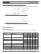
PwrCtrl
SW1 Main
On/Off Switch 1A
F2
1A
Diode
>20A
Resistor
1K, 0.5W
+-
F1
I/O Connector
VMot
to +40V Max
Digital Out
Ground
Ground
Main
Battery
FIGURE 3. Contactor wiring diagram