
Data Sheet

4 HDC24xx Motor Controller Datasheet Version 1.5. October 12, 2015
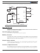
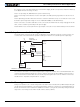
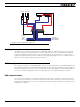
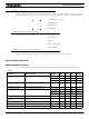
The diagram below shows how to wire the controller and how to turn power On and Off.
Important Warning
Carefully follow the wiring instructions provided in the Power Connection section of the User Manual. The
information on this datasheet is only a summary.
Power Control Wiring for 72V Controllers
Power control line can only be used for powering off when grounded.
Mandatory Connections
It is imperative that the controller is connected as shown in the above diagram in order to ensure a safe and trou-
ble-free operation. All connections shown as thick black lines line are mandatory. The controller must be powered
On/Off using switch SW1on the Yellow wire. Use a suitable high-current fuse F1 as a safety measure to prevent
damage to the wiring in case of major controller malfunction.
Emergency Switch or Contactor
The battery must be connected in permanence to the controller’s Red wires via a high-power emergency switch
or contactor SW2 as additional safety measure. The user must be able to deactivate the switch or contactor at
any time, independently of the controller state.
Precautions and Optional Connections
Note 1: Backup battery to ensure motor operation with weak or discharged batteries, connect a second battery to
the Power Control wire/terminal via the SW1 switch. For 72V version controllers, the power control and ground
connection will only be used as the controller on/off switch. Applying voltage on this line will no longer power on
Motor 1
VMot/Red
PwrCtrl/Yellow
SW1 Main
On/Off Switch 1A
F2
1A
Diode
>20A
Resistor
1K, 0.5W
+-
SW2
Emergency
Contactor or
Cut-off Switch
F1
White/M1+
Green/M1-
White/M2+
Green/M2-
Earth Tab
I/O Connector
VMot/Red
Ground/Black
Ground/Black
Ground/Black
Motor 2
Main
Battery
Backup
Battery
Note 5
Note 6
Do not Connect!
Note 1
Note 4
Note 3 Note 2
FIGURE 2. Powering the controller. Thick lines identify MANDATORY connections