
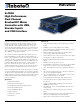
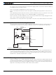
Data Sheet

10 HDC24xx Motor Controller Datasheet Version 1.5. October 12, 2015
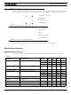
Power Stage Electrical Specifications (at 25oC ambient)
Note 1: Maximum regeneration voltage in normal operation. Never inject a DC voltage from a battery or other fixed source
Note 2: Non-condensing
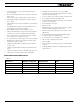
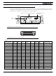
TABLE 7.
Parameter Measure point Models Min Typ Max Units
Battery Leads Voltage Ground to VMot HDC2450(S) 0 (1) 50 Volts
HDC2460 0 (1) 60 Volts
HDC2472(S) 36 (1) 75 Volts
Motor Leads Voltage Ground to M1+, M1-,
M2+, M2-
HDC2450(S) 0 (1) 50 (2) Volts
HDC2460 0 (1) 60 (2) Volts
HDC2472(S) 36 (1) 75 (2) Volts
Power Control Voltage Ground to Power Control
wire
All 0 (1) 65 Volts
Minimum Operating
Volt age
VMot or Pwr Ctrl wires All 9 (3) Volts
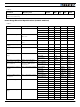
Over Voltage protection
range
Ground to VMot HDC2450(S) 5 50 (4) 50 Volts
HDC2460 5 60 (4) 60 Volts
HDC2472(S) 5 72 (4) 75 Volts
Under Voltage protection
range
Ground to VMot HDC2450(S) 0 5 (4) 50 Volts
HDC2460 0 5 (4) 60 Volts
HDC2472(S) 0 5 (4) 75 Volts
Idle Current Consumption VMot or Pwr Ctrl wires All 50 100 (5) 150 mA
ON Resistance (Excluding
wire resistance)
VMot to M+, plus M- to
Ground at 100% power.
Per channel
HDC2450/60/72 3 mOhm
HDC2450S/72S 1.5 mOhm
Max Current per channel
for 30s
Ch1 or Ch2 Motor current HDC2450/60 150 (6) Amps
HDC2472 120 (6) Amps
HDC2450S 300 (6)(7) Amps
HDC2472S 240 (6)(7) Amps
Continuous Max Current
per channel
Ch1 or Ch2 Motor current HDC2450/60/72 80 (8) Amps
HDC2450S/72S 160 (7)(8) Amps
Current Limit range Ch1 or Ch2 Motor current HDC2450 10 100 (9) 150 Amps
HDC2460 10 100 (9) 150 Amps
HDC2472 10 100 (9) 120 Amps
HDC2450S 10 200 (9) 300 (7) Amps
HDC2472S 10 200 (9) 240 (7) Amps
Stall Detection Amps
range
Ch1 or Ch2 Motor current HDC2450 10 100 (9) 150 Amps
HDC2460 10 100 (9) 150 Amps
HDC2472 10 100 (9) 120 Amps
HDC2450S 10 200 (9) 300 (7) Amps
HDC2472S 10 200 (9) 240 (7) Amps
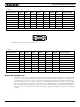
TABLE 6.
Parameter Measure point Models Min Typ Max Units