
Data Sheet

Status LED Flashing Patterns
GDC3xxx Motor Controller Datasheet 9
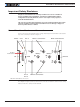
Ethernet Communication
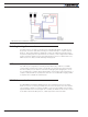
Ethernet communication is only available on the E versions of the controller. The con-
nection port is located on the top of the unit for easy and rapid access. Communication
occurs via TCP/IP. Commands can be in Serial over TCP and Modbus TCP. Serial over TCP is
the preferred method to access all native commands.
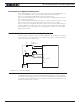
Two LEDs are present on the Ethernet jack, as shown in Figure 7. The left Yellow LED
will be On when operating as 100 Mbps connection and Off when as 10 Mbps. The right
Green LED will blink when data activity is present.
FIGURE 7. Ethernet LED Configuration
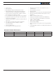
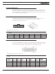
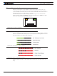
Status LED Flashing Patterns
After the controller is powered on, the Power LED will tun on, indicating that the controller
is On. The Status LED will be flashing at a 2 second interval. The flashing pattern and color
provides operating or exception status infor mation.
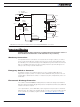
FIGURE 8. Normal Operation Flashing Patterns
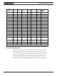
FIGURE 9. Exception or Fault Flashing Patterns
Additional status information may be obtained by monitoring the controller with the PC
utility.