
Data Sheet

6 GDC3xxx Motor Controller Datasheet Version 1.2 December 28, 2018
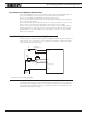
Controller Mounting
During motor operation, the controller will generate heat that must be evacuated. The pub-
lished amps rating can only be fully achieved if adequate cooling is provided. Good con-
duction cooling can be achieved by having the bot tom surface of the case making contact
with a metallic surface (chassis, cabinet).
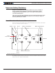
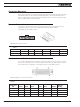
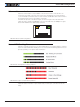
Encoder Connection
Connection to the Encoders is done using a special connector on the front side of the
controller. The Encoder connector is a 6-pin Molex Microfit 3.0, ref. 43645.
Pin assignment are in Table 1, below.
61
6
1
FIGURE 4. Encoder Connector
TABLE 1.
Pin Number 1 2 3 4 5 6
Signal 5V Enc 3A Enc 1B Enc 1A Ground
Signal 5V Enc 3B Enc 2B Enc 2A Ground
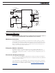
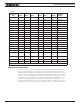
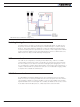
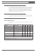
Commands and I/O Connections
Connection to RC Radio, Microcomputer, Joystick and other low current sensors and actu-
ators is done via the 25 connector. The functions of many pins vary depending on control-
ler model and user configuration. Pin assignments are found in Table 2, below.
FIGURE 5. Main Connector Pin Locations
TABLE 2.
Connector
Pin Power Dout Com Pulse Ana Dinput
Default
Config
1 GND
14 5VOut
2 RS TxD RS232Tx
15 RC1 ANA1 DIN1 RCRadio1