
Data Sheet

4 GDC3xxx Motor Controller Datasheet Version 1.2 December 28, 2018
Controller Power
Motor Wires
VMot GroundGround
(top)
Power Control
VMot
PwrCtrl
SW1 Main
On/Off Sw itch 1A
F2
1A
Diode
>20A
Resi stor
1K, 0.5W
+-
SW2
Emergency
Contactor or
Cut-off Switch
F1
I/O Connector
Ground
Ground
Main
Battery
Backup
Battery
Note 6
Do not Connect!
Note 1
2 etoN 3 etoN
U1 U2 V1 V2 W1 W2
Note 5
Note 4
Motor1
a
Enc 1
Enc 2
Enc 3
Motor 3
Motor 2
a
U1
V1
U2
V2
W1
W2
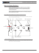
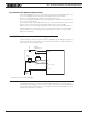
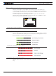
FIGURE 2. Powering the Controller. Thick lines identify MANDATORY connections
Important Warning
Carefully follow the wiring instructions provided in the Power Connection section of
the User Manual. The information on this datasheet is only a summary.
Mandatory Connections
It is imperative that the controller is connected as shown in Figure 2, above, in order to
ensure a safe and trou ble-free operation. All connections shown as thick black lines line
are mandatory. The controller must be powered On/Off using switch SW1on the Pwr Ctrl
tab. Use a suitable high-current fuse F1 as a safety measure to prevent damage to the
wiring in case of major controller malfunction.
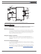
Emergency Switch or Contactor
The battery must be connected in permanence to the controller’s VMot tabs via a
high-power emergency switch or contactor SW2 as additional safety measure. The user
must be able to deactivate the switch or contactor at any time, independently of the con-
troller state.
Electrostatic Discharge Protection
In accordance with IEC 61000-6-4, Roboteq Motor Controllers are designed to withstand
ESD up to 4kV touch and 8kV air gap. This protection is implemented without any additional
external connections required.
Some specifications, such as EN12895, require a higher level of protection. To maximize
ESD protection, up to 8kV touch and 15kV air gap, you may connect the metallic heatsink
of the controller to your battery negative terminal. See App Note 062918 for example
connections.