
Data Sheet

12 GDC3xxx Motor Controller Datasheet Version 1.2 December 28, 2018
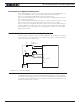
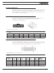
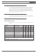
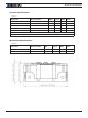
Command, I/O and Sensor Signals Specifications
TABLE 5.
Parameter Measure point Min Typ Max Units
Main 5V Output Voltage Ground to 5V pins on 4.6 4.75 4.9 Volts
5V Output Current 5V pins on RJ45 and DSub15 200 (1) mA
Digital Output Voltage Ground to Output pins 60 Volts
Output On resistance Output pin to ground 0.25 0.5 Ohm
Output Short circuit threshold Output pin 1. 7 3.5 Amps
Digital Output Current Output pins, sink current 1. 5 Amps
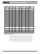
Input Impedances (except
DIN11-19)
AIN/DIN Input to Ground 53 kOhm
Digital Input 0 Level Ground to Input pins -1 1 Volts
Digital Input 1 Level Ground to Input pins 3 30 Volts
Analog Input Range Ground to Input pins 0 5.1 Volts
Analog Input Precision Ground to Input pins 0.5
%
Analog Input Resolution Ground to Input pins 1
mV
Pulse durations Pulse inputs 20000 10
us
Pulse repeat rate Pulse inputs 50 250
Hz
Pulse Capture Resolution Pulse inputs 1
us
Frequency Capture Pulse inputs 100 1000
Hz
Note 1: Sum of all 5V Out outputs
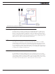
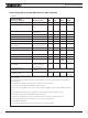
Operating & Timing Specifications
TABLE 6.
Parameter Measure Point Min Typical Max Units
Command Latency Command to output change 0 0.5 1 ms
PWM Frequency Motor Output 10 18 20 kHz
Closed Loop update rate Internal 1000 Hz
RS232 baud rate Rx & Tx pins 115200 (1) Bits/s
RS232 Watchdog timeout Rx pin 1 (2) 65000 ms
Note 1: 115200, 8-bit, no parity, 1 stop bit, no flow control
Note 2: May be disabled with value 0
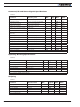
Scripting
TABLE 7.
Parameter Measure Point Min Typical Max Units
Scripting Flash Memory Internal 32000 Bytes
Max Basic Language programs Internal 2000 3000 Lines
Integer Variables Internal 4096 Words (1)
Boolean Variables Internal 8192 Symbols
Execution Speed Internal 50000 100000 Lines/s
Note 1: 32-bit words