
Data Sheet
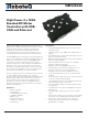

10 GDC3xxx Motor Controller Datasheet Version 1.2 December 28, 2018
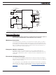
Battery Backed Clock and Variables
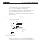
The controller includes a real-time clock/calendar and RAM storage for user variables. Both
the clock and the RAM storage require a battery to continue running and for the stored
data not to be lost while the controller is powered down. The battery is not installed by
Roboteq. Users who wish to use the clock and/or battery backed RAM variables must
install a battery themselves. The battery socket can be reached by removing the 6 screws
that are holding the cover. Lift the cover to reach the board and insert a 3V, 12.5mm coin-
style battery. Use battery type CR1225 or equivalent.
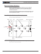
Measured Amps
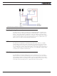
The controller includes Amps sensors in line with the motor terminals and on the battery
ground terminals. Both Motor Amps and Battery Amps are therefore measured with precision.
Electrical Specifications
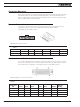
Absolute Maximum Values
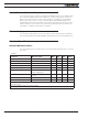
The values Table 3, below, should never be exceeded, permanent damage to the controller
may result.
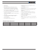
TABLE 3.
Parameter Measure point Min Typ Max Units
Battery Leads Voltage Ground to VBat 63 Volts
Reverse Voltage on Battery Leads Ground to VBat -1 Volts
Power Control Voltage Ground to Pwr Control wire 63 Volts
Motor Leads Voltage Ground to U, V, W wires 63 (1) Volts
Digital Output Voltage Ground to Output pins 60 Volts
Analog and Digital Inputs Voltage Ground to any signal pin on
15-pin & Hall inputs
30 Volts
RS232 I/O pins Voltage External voltage applied to Rx/
Tx pins
30(2) Volts
Case Temperature Case -40 85 ºC
Humidity Case 100 (2) %
Note 1: Maximum regeneration voltage in normal operation. Never inject a DC voltage from a battery or
other fixed source
Note 2: No voltage must be injected on TxD pin