
Data Sheet


Copyright © Roboteq Inc. 2018. All Rights Reserved. 3
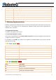
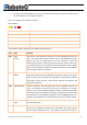
1.5.2 Modbus ASCII frame format
Name
Length (bytes)
Description
Start
1
Starts with colon : (ASCII hex value is 3A)
Address
2
Node address in hex
Function
2
Function code in hex
Data
n x 2
n is the number of data bytes, it depends on function
LRC
2
Checksum (Longitudinal redundancy check)
End
2
CR/LF
Address, function, data, and LRC are all capital hexadecimal readable pairs of characters representing 8-bit
values (0–255). For example, 122 (7 × 16 + 10) will be represented as 7A.
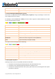
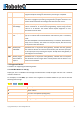
1.5.3 Modbus TCP frame
Name
Length (bytes)
Description
Transaction ID
2
For synchronization between messages of server and client
Protocol ID
2
0 for Modbus/TCP
Length
2
Number of remaining bytes in this frame
Unit ID
1
Node address
Function
1
Function code
Data
n
n is the number of data bytes, it depends on function
Unit identifier is used with Modbus/TCP devices that are composites of several Modbus devices, e.g. on
Modbus/TCP to Modbus RTU gateways. In such case, the unit identifier tells the Slave Address of the
device behind the gateway. Natively Modbus/TCP-capable devices usually ignore the Unit Identifier.
1.6 Function Codes
Modbus protocol defines several function codes for accessing Modbus registers. There are four different
data blocks defined by Modbus, and the addresses or register numbers in each of those overlap. Therefore,
a complete definition of where to find a piece of data requires both the address (or register number) and
function code (or register type).
The function codes most commonly recognized by Modbus devices are indicated in the table below. This is
only a subset of the codes available - several of the codes have special applications that most often do not
apply.
Function Code
Register Type
1
Read Coil
2
Read Discrete Input