
Data Sheet


Copyright © Roboteq Inc. 2018. All Rights Reserved. 9
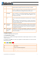
Name
Description
00 03
Transaction ID.
00 00
Protocol Identifier (0x0000 for TCP).
00 06
Number of bytes in the record.
01
Node address
04
Function code (Read Input Registers)
20 C1
Register address for reading VAR1
00 02
Length of registers to be read (must be 2)
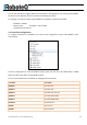
The response for this message will be as following:
00 03 00 00 00 0D 01 04 04 00 00 12 34
Name
Description
00 03
Transaction ID.
00 00
Protocol Identifier (0x0000 for TCP).
00 0D
Number of bytes in the record (13 bytes).
01
Node address
04
Function code (Read Input Registers)
04
Total bytes read (always 4 bytes)
00 00 12 34
Value in big Indian notation (MSB first).
2.2.3 Modbus RS232/RS485 ASCII
Modbus ASCII marks the start of each message with a colon character ":" (hex 3A). The end of each
message is terminated with the carriage return and line feed characters (hex 0D and 0A).
In Modbus ASCII, each data byte is split into the two bytes representing the two ASCII characters in the
Hexadecimal value.
Modbus ASCII is terminated with an error checking byte called an LRC or Longitudinal Redundancy Check
(See appendix B).
For examples, to read VAR1, you need to read 2 registers from address 0x20C1 so you need to send the
following ASCII message:
:010420C1000218<CRLF>
Name
Description
':'
Start of message - 0x3A