The Roboteq Modbus Implementation User Manual V1.1, December 21, 2017 Visit www.roboteq.com to download the latest revision of this manual ©Copyright 2017 Roboteq, Inc Copyright © Roboteq Inc. 2018. All Rights Reserved.
Table of Contents 1. Introduction....................................................................................................................................... 1 1.1 What is Modbus ...................................................................................................................................... 1 1.2 Modbus object types .............................................................................................................................. 1 1.3 Protocol versions ..........
1. Introduction The Roboteq Modbus Implementation User manual contains information about how Roboteq implemented Modbus protocol in controllers. 1.1 What is Modbus Modbus is a serial communication protocol developed by Modicon published by Modicon in 1979 for use with its programmable logic controllers (PLCs). In simple terms, it is a method used for transmitting information over serial lines between electronic devices.
• Modbus over TCP/IP or Modbus over TCP or Modbus RTU/IP: This is a Modbus variant that differs from Modbus TCP in that a checksum is included in the payload as with Modbus RTU. Data model and function calls are identical for the previous 4 variants of protocols; only the encapsulation is different. 1.4 Communication and devices Each device intended to communicate using Modbus is given a unique address.
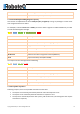
1.5.2 Modbus ASCII frame format Name Length (bytes) Description Start 1 Starts with colon : (ASCII hex value is 3A) Address 2 Node address in hex Function 2 Function code in hex Data nx2 n is the number of data bytes, it depends on function LRC 2 Checksum (Longitudinal redundancy check) End 2 CR/LF Address, function, data, and LRC are all capital hexadecimal readable pairs of characters representing 8-bit values (0–255). For example, 122 (7 × 16 + 10) will be represented as 7A. 1.5.
3 Read Holding Registers 4 Read Input Registers 5 Write Single Coil 6 Write Single Holding Register 15 Write Multiple Coils 16 Write Multiple Holding Registers 2. Roboteq Implementation Roboteq’s implementation of Modbus doesn’t contain all supported functions and modes but contains only subset of it. I this section we are introducing the supported modes and functions implemented in Roboteq’s micro controllers. 2.1 Supported Functions Controllers only supports two functions: 2.1.
00 00 12 34 Value in big Indian notation (MSB first). F6 F3 Cyclic redundancy check (CRC-16-IBM) 2.1.2 Write Multiple Holding Registers (0x10) This function is implemented to write exactly 4 bytes (2 registers). Issuing any messages to write other than 2 registers will have no effect.
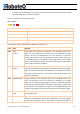
• The request is received without an error, but cannot be processed by the slave for another reason. The slave replies with an exception response. Here is an example of an exception response: 0A 81 02 B053 0A 81 02 B053 Name Description 0A Node address 81 Function code with the highest bit set. 02 The exception code.
timeout error from occurring in the master. The master can next issue a Poll Program Complete message to determine if processing is completed. 0x06 Slave Device Busy Specialized use in conjunction with programming commands. The slave is engaged in processing a long-duration program command. The master should retransmit the message later when the slave is free.. 0x07 Negative Acknowledge The slave cannot perform the program function received in the query.
2B F7 Cyclic redundancy check (CRC-16-IBM) The response for this message will be as following: 01 04 04 00 00 12 34 F6 F3 Name Description 01 Node address 04 Function code (Read Input Registers) 04 Total bytes read (always 4 bytes) 00 00 12 34 Value in big Indian notation (MSB first). F6 F3 Cyclic redundancy check (CRC-16-IBM) 2.2.
Name Description 00 03 Transaction ID. 00 00 Protocol Identifier (0x0000 for TCP). 00 06 Number of bytes in the record. 01 Node address 04 Function code (Read Input Registers) 20 C1 Register address for reading VAR1 00 02 Length of registers to be read (must be 2) The response for this message will be as following: 00 03 00 00 00 0D 01 04 04 00 00 12 34 Name Description 00 03 Transaction ID. 00 00 Protocol Identifier (0x0000 for TCP). 00 0D Number of bytes in the record (13 bytes).
'0' '1' Node address – 0x01 '0' '4' Function code (Read Input Registers) – 0x04 '2' '0' 'C' '1' Register address for reading VAR1 – 0x20C1 '0' '0' '0' '2' Length of registers to be read (must be 2) – 0x0002 '1' '8' LRC End of message, carriage return and line feed – 0x0D0A The response for this message will be as following: :01040400001234DE Name Description ':' Start of message - 0x3A '0' '1' Node address – 0x01 '0' '4' Function code (Read Input Registers) – 0x04 '0' '4' R
You can also calculate the register address from the tables in the appendix A, you need to get the Modbus ID value from the table then add to it the desired command/query index. For example, the read user integer variable Modbus ID is 0x20C0, to get the first variable: - ModbusID = 0x20C0. Add the index → 0x20C0 + 0x01 = 0x20C1 Use 0x20C1 as the address. 2.
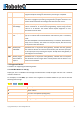
3. Appendix A: Commands Mapping 3.
CB VAR SR CR BCR BS BSR BA V D DI AI PI T F FS FF B DO E CIS CIA CIP TM LK TR K DR AIC PIC MA MGD MGT MGM MGS MGY FM HS QO EO RMA RMG RMM 0x2105 0x2106 0x2107 0x2108 0x2109 0x210A 0x210B 0x210C 0x210D 0x210E 0x6400 0x6401 0x6403 0x210F 0x2110 0x2111 0x2112 0x2115 0x2113 0x2114 0x2116 0x2117 0x2118 0x2119 0x2124 0x2125 0x211A 0x211B 0x6402 0x6404 0x211C 0x211D 0x211E 0x211F 0x2120 0x2121 0x2122 0x2123 0x2126 0x2127 0x2128 0x2129 0x212A Copyright © Roboteq Inc. 2018. All Rights Reserved.
ML TS MRS MZ PK RF FIN GY ANG SCC ICL FC SL 0x212B 0x212C 0x212D 0x212E 0x212F 0x2130 0x2137 0x2131 0x2132 0x2133 0x2134 0x2135 0x2136 0x2560 0x2580 0x25A0 0x25C0 0x25E0 0x2600 0x26E0 0x2620 0x2640 0x2660 0x2680 0x26A0 0x26C0 9568 9600 9632 9664 9696 9728 9952 9760 9792 9824 9856 9888 9920 4.
0x01, 0xC0, 0x80, 0x41, 0x00, 0xC1, 0x81, 0x40, 0x00, 0xC1, 0x81, 0x40, 0x01, 0xC0, 0x80, 0x41, 0x01, 0xC0, 0x80, 0x41, 0x00, 0xC1, 0x81, 0x40, 0x00, 0xC1, 0x81, 0x40, 0x01, 0xC0, 0x80, 0x41, 0x00, 0xC1, 0x81, 0x40, 0x01, 0xC0, 0x80, 0x41, 0x01, 0xC0, 0x80, 0x41, 0x00, 0xC1, 0x81, 0x40, }; const u8 modbus_crc_lo[] = { 0x00, 0xC0, 0xC1, 0x01, 0xC3, 0x03, 0x02, 0xC2, 0xC6, 0x06, 0x07, 0xC7, 0x05, 0xC5, 0xC4, 0x04, 0xCC, 0x0C, 0x0D, 0xCD, 0x0F, 0xCF, 0xCE, 0x0E, 0x0A, 0xCA, 0xCB, 0x0B, 0xC9, 0x09, 0x08, 0xC8,
u16 modbus_calcCRC(const u8 *p, int length) { u8 hi = 0xFF; u8 lo = 0xFF; while (length--) { u8 i = lo ^ *p++; lo = hi ^ modbus_crc_hi[i]; hi = modbus_crc_lo[i]; } return (u16) (hi << 8) | lo; } u8 modbus_calcLRC(u8* inputBuffer, int length) { u8 sum = 0; for(int i = 0; i < length; i++) { sum += inputBuffer[i]; } return ~sum + 1; } Copyright © Roboteq Inc. 2018. All Rights Reserved.