
Data Sheet

Connection to SSI Absolute Encoder
GBL2xxx Motor Controller Datasheet 7
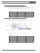
TABLE 1.
Pin Number 1 2 3 4 5 6
Signal 5V Hall C Hall B Hall A Ground
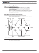
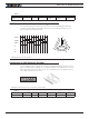
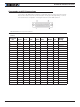
Hall Sensor vs Motor Output sequencing
The controller requires the Hall sensors inside the motor to be 120 degrees apart. The
controller’s 3-phase bridge will activate each of the motor winding according to the se-
quence shown in the Figure 6, below.
FIGURE 6. Hall Sensors Sequence
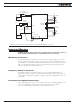
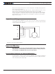
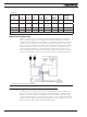
Connection to SSI Absolute Encoder
In Sinusoidal Mode, the controller can use motors equipped with absolute angle sensors
with SSI interface. When enabled, the SSI signals are found on the 6-pin Molex connector
that is otherwise used for the Hall Sensors. The controller issues a clock signal to, and re-
ceives data signal from the encoder.
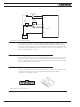
FIGURE 7. Hall Sensor Connector Used for SSI Encoders
TABLE 2.
Pin Number 1 2 3 4 5 6
Signal 5V Clock - Clock + Data - Data + Ground
U
VW
1234561
4
2
5
3
6
4
1
5
2
6
3
Hall A
Hall B
Hall C
U
V
W
+
--
-- --
-- --
--
++ ++
++ ++
++ +
61
6
1